Eureka AIR delivers breakthrough ideas for toughest innovation challenges, trusted by R&D personnel around the world.

Machine tool

A machine tool and tool technology, which is applied in the direction of manufacturing tools, metal processing machinery parts, mechanical equipment, etc., can solve problems such as vibration, affecting the service life of the machine, and uncomfortable users, so as to reduce the risk of overload and reduce overload. Risk, the effect of reducing the risk of vibration

Active Publication Date: 2014-10-29
C & E PANYIN CO LTD
View PDF7 Cites 5 Cited by
  • Summary
  • Abstract
  • Description
  • Claims
  • Application Information

AI Technical Summary

Problems solved by technology

[0003] Especially in machine tools with an oscillating drive, but also in certain machine tools with a rotationally driven tool drive shaft (such as angle handle hand grinders) there is the problem that vibrations can occur which adversely affect the machine's service life and will make the user feel uncomfortable
[0007] But with such an embodiment only a longitudinal balance in the area of ​​the drive line is achieved

Method used


Image

  • Machine tool
  • Machine tool
  • Machine tool

Examples


Embodiment Construction

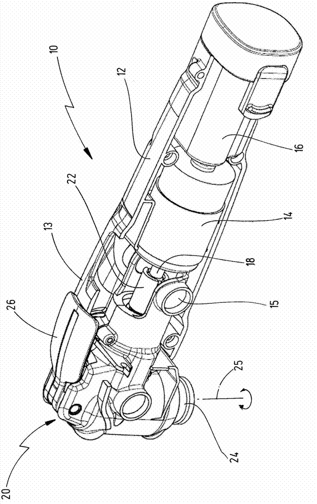
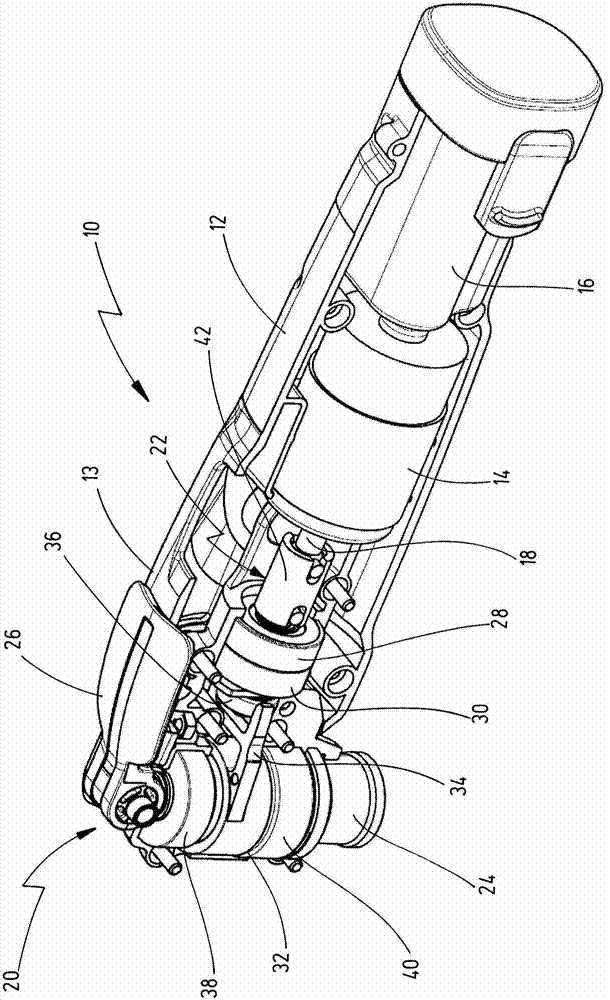
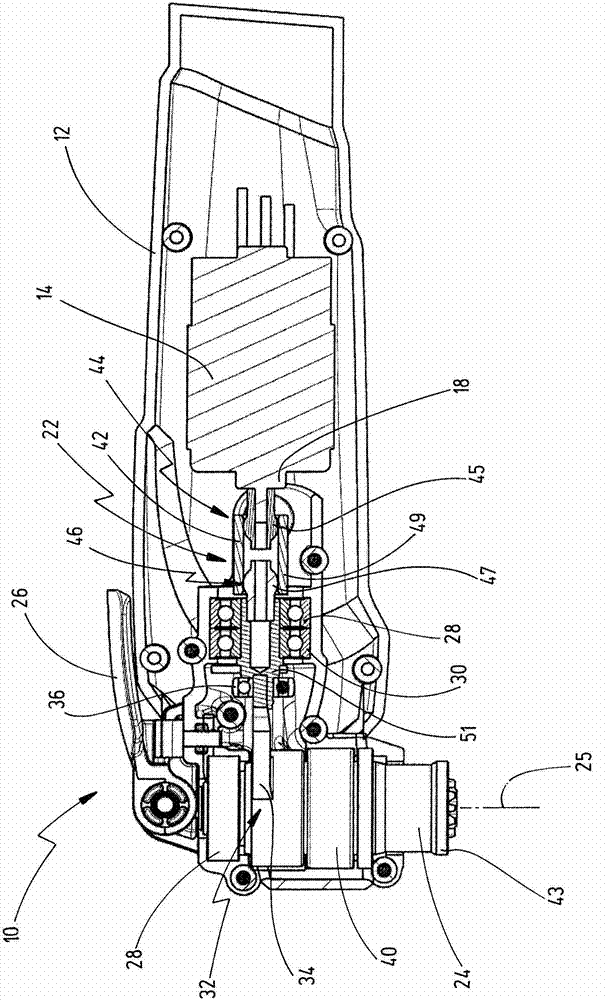
[0042] Figure 1-3 A first embodiment of the power tool according to the invention is shown, generally designated 10 . It is an oscillatingly driven power tool 10 having a motor housing 12 in which a drive motor 14 is accommodated and a gear housing 13 in which a tool drive shaft 24 is accommodated. The rotational movement of the motor shaft 18 is converted via the coupling device 22 and the corresponding coupling gear 20 into an oscillating drive movement of the tool drive shaft 24 about its longitudinal axis 25 .

[0043] On the outer end of the tool drive shaft 24 (the outer end protruding outward from the housing 12) a tool receiving device 43 is provided ( image 3 ), on which a corresponding tool, such as a grinding tool, a cutting tool or a sawing tool, can be fixed by means of a quick clamping device (not shown) with the aid of a clamping rod 26 . The tool drive shaft 24 is supported on the housing 12 by means of two bearings 38, 40 ( figure 2 and 3 ).

[0044]Th...


PUM


Abstract

A motor-driven machine tool has a drive motor, the motor shaft of which is driven in rotation, with a tool drive shaft, which is driven in rotation or in oscillation about its longitudinal axis, and with a coupling drive for converting the rotational movement of the motor shaft into a driving movement of the tool drive shaft. Furthermore, a coupling is provided, which compensates an angular offset or change in position between the motor shaft and tool drive shaft which deviates from an axially parallel or right-angled arrangement of the two shafts.

Description

technical field [0001] The invention relates to a motor-driven machine tool having a drive motor whose motor shaft is rotationally driven, a tool drive shaft which is driven rotationally or oscillatingly about its longitudinal axis, and A coupling transmission is provided for converting the rotational movement of the motor shaft into a drive movement of the tool drive shaft. Background technique [0002] Such power tools have been known for decades and are used in various ways, in particular as hand-held power tools. There are machines in which the tool drive shaft performs a rotary motion, such as drills or angle handle hand grinders. Furthermore, machines with an oscillating drive movement of the tool drive shaft have been increasingly used in the past few years, wherein the tool drive shaft can be driven oscillatingly about its longitudinal axis. Such oscillating machine tools are used in a variety of ways for grinding, cutting, sawing, and the like. [0003] Especiall...

Claims


Application Information

Patent Timeline
Patent Type & Authority Applications(China)
IPC IPC(8): B25F5/00B24B23/02
CPCF16H25/16B25F5/001Y10T74/18296B24B23/04B24B23/02F16D3/2052B25F5/00B23Q5/027B27B19/006B23D51/16
Inventor 拉尔夫·西鲍尔
Owner C & E PANYIN CO LTD
Why Eureka
Eureka Blog
Learn More