
Scroll saw driven by electromagnets

A technology of electromagnet and jig saw, applied in the field of jig saw, can solve the problems of large lateral component force, power consumption and wear, etc., and achieve the effects of low cost, extended service life and simple structure

Inactive Publication Date: 2014-10-29
CHONGQING YIYANXIANG BUILDING MATERIAL CO LTD
View PDF9 Cites 5 Cited by
  • Summary
  • Abstract
  • Description
  • Claims
  • Application Information

AI Technical Summary

Problems solved by technology

Although this kind of jigsaw is said to be driven by steel wire, it is actually driven by a slider and an eccentrically installed roller. This driving method uses a rotating part to drive a small shaft eccentrically fixed on the flywheel as the active part, so that the side Defects of large component force and severe wear due to power consumption

Method used


Image

  • Scroll saw driven by electromagnets
  • Scroll saw driven by electromagnets

Examples


Embodiment 1

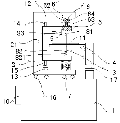
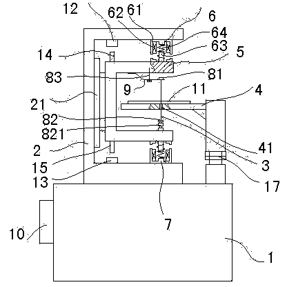
[0026] Embodiment 1: as figure 1 As shown, a jigsaw driven by an electromagnet includes a base 1, a frame 2, a saw blade 3 and a worktable 4, the workbench 4 is connected to the base 1, the frame 2 is a U-shaped structure, and the frame 2 is movable placed on the base 1; the middle part of the inside of the frame 2 is fixed with a guide rail 21 along the up and down direction, and the guide rail 21 is equipped with a bow-shaped saw frame 5; the upper port part of the inside of the frame 2 is connected with an upper electromagnet 6, The lower port position inside the frame 2 is connected with a lower electromagnet 7, the upper electromagnet 6 and the lower electromagnet 7 are each composed of a yoke 61, a solenoid 62 and an armature core 63, and the outer bottom of the yoke 61 is connected to the frame 2 Fixed connection, one end of the armature core 63 is fixedly connected with the outside of the saw frame 5, and the cylindrical coil spring 64 is covered with a gap between th...

Embodiment 2

[0033] Embodiment 2: The solenoids of the upper electromagnet 6 and the lower electromagnet conduct in turn, and the directions of their active forces are opposite, and all the other structures are the same as in Embodiment 1.

Embodiment 3

[0034] Embodiment 3: The frame and the machine base are fixedly connected, the corresponding parts of the workbench and the saw blade have a through hole 41 that can pass through the saw blade, and the rest of the structure is the same as that of Embodiment 1, such as figure 2 shown.


PUM


Abstract

The invention provides a scroll saw driven by electromagnets. The scroll saw comprises a machine base, a machine frame, a saw blade and a work table, the work table is connected with the machine base, the machine frame is arranged on the machine base, the inner side of the machine frame is provided with a guide rail and is provided with an arch saw frame, the upper end opening of the inner side of the machine frame is connected with the upper electromagnet, the lower end opening of the inner side of the machine frame is connected with the lower electromagnet, each electromagnet is formed by a yoke, a solenoid and an armature core, the yokes are connected with the machine frame, the armature cores are connected with the outside of the saw frame, a spring is arranged between each armature core and the corresponding solenoid in a sleeved mode, one end of each spring abuts against the bottom of the corresponding yoke, the other end of each spring abuts against the outside of the saw frame, the position, corresponding to the upper electromagnet, on the inner side of the saw frame is connected with an upper hook through a spring plate, the position, corresponding to the lower electromagnet, of the lower portion of the saw frame is connected with a lower hook, the saw blade is hung on the upper hook and the lower hook, one end of the spring plate is fixedly connected with the saw frame, the other end of the spring plate is hung on the upper hook through a round hole, the middle of the upper hook is provided with a shoulder abutting against the upper end face of the round hole, the middle of the spring plate is provided with a regulating screw, and currents passing through the solenoids are controlled by an electrical appliance. The scroll saw has the advantages that movement is stable, efficiency is high, traction force is balanced and saw teeth can be protected.

Description

technical field [0001] The invention relates to a curve saw for woodworking machinery, in particular to a curve saw driven by an electromagnet. Background technique [0002] In the machine, the reciprocating linear motion mechanism is often used to change the motion type or transmit the motion, or as an actuator to complete the functional action required by the production process, and at the same time meet the requirements of speed and acceleration. For example, crank slider reciprocating linear movement mechanism, cam type reciprocating linear movement mechanism, these reciprocating linear movement mechanisms have a common feature, that is, they all use rotating parts as active parts to drive parts such as sliders to move along linear guide rails to obtain reciprocating straight lines. sports. Although these transmission mechanisms have many advantages, they are large in size, complex in structure and heavy, and consume power due to large lateral component forces and also ...

Claims


Application Information

Patent Timeline
Patent Type & Authority Applications(China)
IPC IPC(8): B27B19/04
Inventor 章建成
Owner CHONGQING YIYANXIANG BUILDING MATERIAL CO LTD
Learn More