Hydraulic power type pulp flowing box

A technology of convergent flow and turbulent flow generator, applied in the field of machinery

Inactive Publication Date: 2014-10-29
XIAN WEIYA PAPER MACHINERY
View PDF10 Cites 2 Cited by
  • Summary
  • Abstract
  • Description
  • Claims
  • Application Information

AI Technical Summary

Problems solved by technology

[0003] The present invention provides a hydraulic headbox, which can effectively overcome the inaccurate connection between the spray port and subsequent equipment of the hydraulic headbox in the prior art , resulting in the unsatisfactory defect of slurry flow on the Internet

Method used


Image

  • Hydraulic power type pulp flowing box
  • Hydraulic power type pulp flowing box
  • Hydraulic power type pulp flowing box

Examples


Embodiment Construction

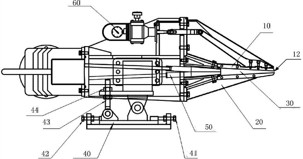
[0022] Wherein, the turbulence generator 50, the local fine-tuning mechanism 60, the upper lip 10 and the lower lip 20 are arranged on the adjustable base 40; the adjustable base 40 can adjust the headbox to move up and down and back and forth. refer to figure 1 , the adjustable base 40 is equipped with a first bolt 41, a second bolt 42, a screw rod 43 and a nut 44, and adjusting the first bolt 41 and the second bolt 42 can make the headbox move back and forth; adjust the vertical screw rod 43 Nut 44 can make the headbox move up and down.

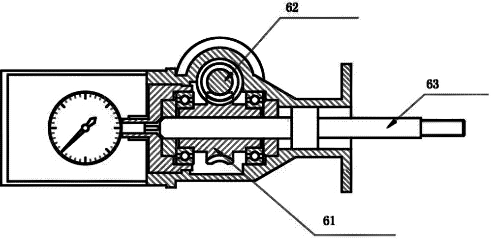
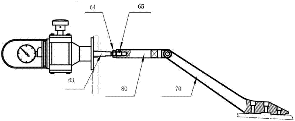
[0023] The local fine-tuning mechanism 60 is connected to the upper lip 10 .

[0024] A converging channel 30 is formed between the upper lip 10 and the lower lip 20 .

[0025] The turbulence generator 50 receives the converging channel 30 behind. refer to figure 1 , the turbulent flow generator includes at least two groups of stainless steel tube bundles, the inlet end of each stainless steel tube bundle is a circular port, and the o...


PUM


Abstract

The invention discloses a hydraulic power type pulp flowing box applied to the field of machines. The purpose is to overcome the defect that in the prior art, a pulp jetting opening of a hydraulic power type pulp flowing box and follow-up equipment are inaccurately connected in a butt joint mode, so that the effect of jetting pulp flows on a net is not ideal. The pulp flowing box comprises an upper lip plate, a lower lip plate, a converging flow channel, an adjustable base, a turbulence generator and a local micro-adjustment mechanism. The hydraulic power type pulp flowing box is suitable for paper making machines.

Description

technical field [0001] The invention relates to the mechanical field, in particular to a hydraulic headbox. Background technique [0002] The headbox is a key part of a modern paper machine, which can effectively disperse fibers, prevent fiber precipitation and re-flocculation, and effectively improve the uniformity of paper sheets. Its structure and properties play a decisive role in the formation of paper sheets and the quality of paper. The hydraulic headbox is a kind of headbox, and its important part is the turbulence generator. The function of the turbulence generator is to generate a reasonable micro-turbulence in the slurry flow, so that the fibers can be fully decomposed, avoid flocculation, and improve The quality of the sheets of paper. The slurry flow out of the turbulence generator passes through the spray lip of the headbox and sprays the slurry onto the net. Due to the high speed of the vehicle, the time for the stock flow to be sprayed from the headbox to ...

Claims


Application Information

Patent Timeline
Patent Type & Authority Applications(China)
IPC IPC(8): D21F1/02
Inventor 李晓宁卢俊华牛嘉鸿李新强
Owner XIAN WEIYA PAPER MACHINERY
Why Eureka
Try Eureka