

Hydraulic automatic gearbox gear-shifting control method and system
A technology of automatic transmission and control method, which is applied in the direction of transmission control, transmission, fluid transmission, etc., can solve the problems that affect the smoothness of shifting, and the impact of shifting is easy to occur, so as to improve smoothness and reduce shifting impact effect
- Summary
- Abstract
- Description
- Claims
- Application Information
AI Technical Summary
Problems solved by technology
Method used
Image

Examples
Embodiment
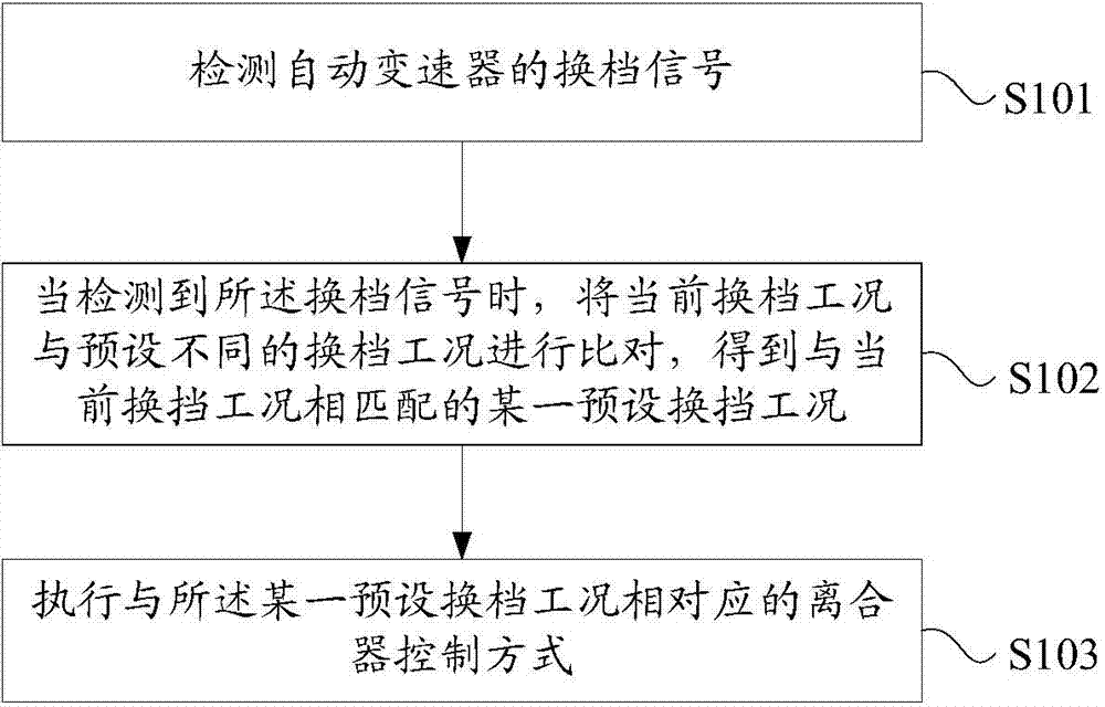
[0053] see figure 1 , figure 1 It is a flow chart of a gear shift control method for a hydraulic automatic transmission provided by an embodiment of the present invention. Such as figure 1 As shown, the method includes:
[0054] Step S101: detecting the shift signal of the automatic transmission;
[0055] Specifically, the shift signal of the automatic transmission from the automatic transmission cooperative control system is detected.
[0056] Step S102: When the shift signal is detected, compare the current shifting condition with preset different shifting conditions to obtain a preset shifting condition that matches the current shifting condition ;
[0057] Specifically, the preset different shifting working conditions include: power upshifting working condition, power downshifting working condition, powerless upshifting working condition and powerless downshifting working condition. The working condition of power upshift refers to the working condition in which the g...
PUM
 Abstract
Description
Claims
Application Information