Gear-hydraulic pressure-pyramid integrated multi-mode composite transmission device

A compound transmission and hydraulic transmission technology, which is applied in the directions of fluid transmission, transmission, transmission control, etc., can solve the problems of limited transmission ratio variation range, fixed transmission ratio and high requirements.

Pending Publication Date: 2021-09-14
JIANGSU UNIV
View PDF0 Cites 4 Cited by
  • Summary
  • Abstract
  • Description
  • Claims
  • Application Information

AI Technical Summary

Problems solved by technology

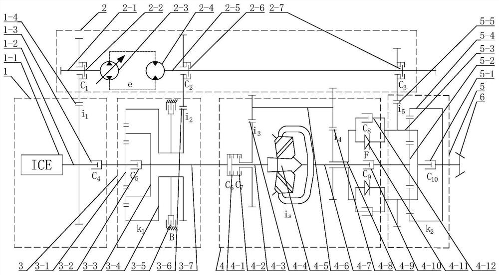
[0003] The variable speed transmission methods currently used in construction machinery generally include gear single-flow transmission, hydraulic single-flow transmission, and hydraulic-gear compound transmission; gear single-flow transmission has high efficiency, but the transmission ratio is fixed, and frequent shifts are required during operation; hydraulic single-flow transmission Flow transmission can easily realize stepless speed regulation, and the transmission torque is large, but its transmission efficiency is low; hydraulic-gear compound transmission is a transmission method in which hydraulic power flow and mechanical power flow are connected in parallel, and it has the advantages of gear transmission. High efficiency and large torque of hydraulic transmission, but it has high requirements for variable hydraulic pump, quantitative hydraulic motor and hydraulic system. Diamond cone continuously variable transmission has the characteristics of large transmission power, strong bearing capacity and low output speed. It is mostly used in construction machinery, but its transmission ratio range is limited
[0004] The existing technology only involves the design of a single-flow transmission device and a compound transmission device in which two single-flow transmissions are connected in parallel, and fails to fully meet the design requirements for multi-mode transmission devices, especially multiple compound modes, under different working conditions of construction machinery.

Method used


Image

  • Gear-hydraulic pressure-pyramid integrated multi-mode composite transmission device
  • Gear-hydraulic pressure-pyramid integrated multi-mode composite transmission device
  • Gear-hydraulic pressure-pyramid integrated multi-mode composite transmission device

Examples


Embodiment Construction

[0038] The present invention will be further described below in conjunction with the accompanying drawings and specific embodiments, but the protection scope of the present invention is not limited thereto.

[0039] Embodiments of the present invention are described in detail below, examples of which are shown in the drawings, wherein the same or similar reference numerals designate the same or similar elements or elements having the same or similar functions throughout. The embodiments described below by referring to the figures are exemplary and are intended to explain the present invention and should not be construed as limiting the present invention.

[0040] In describing the present invention, it is to be understood that the terms "central", "longitudinal", "transverse", "length", "width", "thickness", "upper", "lower", "axial", The orientation or positional relationship indicated by "radial", "vertical", "horizontal", "inner", "outer", etc. is based on the orientation o...


PUM


Abstract

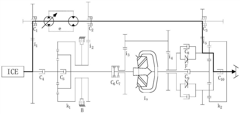
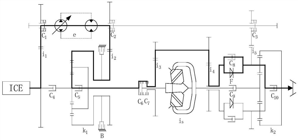
The invention provides a gear-hydraulic pressure-pyramid integrated multi-mode composite transmission device. The gear-hydraulic pressure-pyramid integrated multi-mode composite transmission device comprises an input assembly, a hydraulic transmission mechanism, a front planetary gear mechanism, a pyramid type stepless variable transmission mechanism, a rear planetary gear mechanism, an output assembly, a clutch assembly and a brake assembly. The clutch assembly connects the output end of the input assembly with the input end of the hydraulic transmission mechanism and the input end of the front planetary gear mechanism. The output end of the hydraulic transmission mechanism is connected with the front planetary gear mechanism and the rear planetary gear mechanism through the clutch assembly. The clutch assembly connects the front planetary gear mechanism, the pyramid type stepless variable transmission mechanism, the rear planetary gear mechanism and the output assembly in sequence. The clutch assembly and brake assembly provide the continuous gear ratio between the input assembly and the output assembly. The multi-working-condition operation requirement of engineering machinery can be met, the engine power utilization rate is increased, and the fuel economy is improved.

Description

technical field [0001] The invention relates to the field of variable speed transmission devices, in particular to a multi-mode composite transmission device integrating gears, hydraulic pressure and diamond cones. Background technique [0002] In recent years, with the development of cities and the acceleration of key project construction, construction machinery has a larger market and development space. The operating environment of construction machinery is complex and changeable. It is very important for construction machinery to ensure the power and fuel economy of the vehicle by changing the speed and torque in a timely manner through the variable speed transmission to adapt to the continuous change of the actual load. [0003] The variable speed transmission methods currently used in construction machinery generally include gear single-flow transmission, hydraulic single-flow transmission, and hydraulic-gear compound transmission; gear single-flow transmission has high...

Claims


Application Information

Patent Timeline
Patent Type & Authority Applications(China)
IPC IPC(8): F16H47/08F16H61/04F16H63/30
CPCF16H47/08F16H61/04F16H63/30
Inventor 朱镇曾令新蔡英凤陈龙邓雨林孙晓东田翔王勇曾发林盘朝奉
Owner JIANGSU UNIV
Why Eureka
Try Eureka