Light emitting diode module

A technology of light-emitting diodes and modules, which is applied to the semiconductor devices, optics, light sources and other directions of light-emitting elements to achieve the effect of weakening the intensity, reducing the difference in light intensity and making effective use of it.

Inactive Publication Date: 2014-10-29
ZHANJING TECH SHENZHEN +1
View PDF8 Cites 3 Cited by
  • Summary
  • Abstract
  • Description
  • Claims
  • Application Information

AI Technical Summary

Problems solved by technology

However, this design still needs to install a large number of LEDs. How to increase the light output angle of each LED to reduce the number of LEDs used has been the direction of the industry's efforts to explore.

Method used


Image

  • Light emitting diode module
  • Light emitting diode module
  • Light emitting diode module

Examples


Embodiment Construction

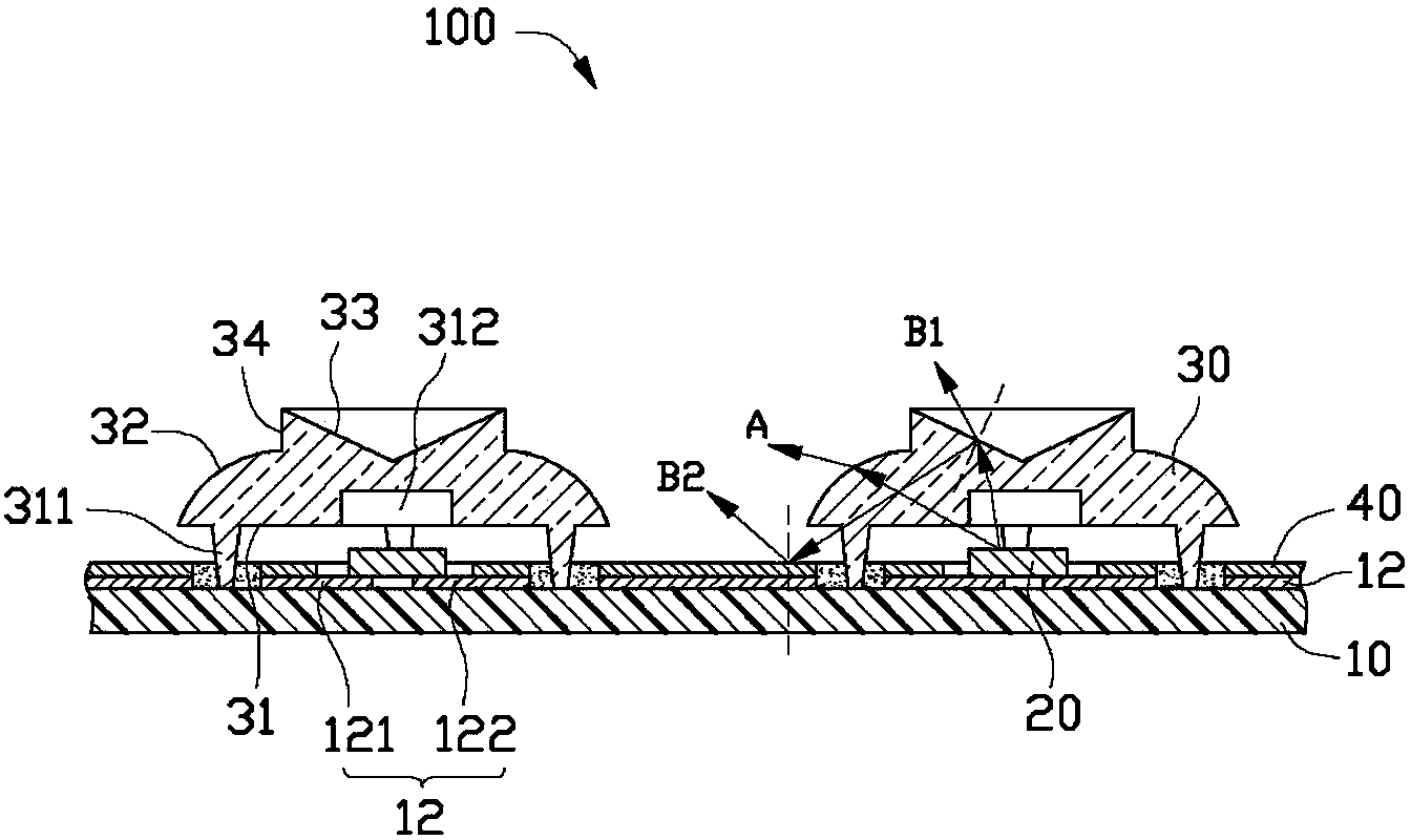
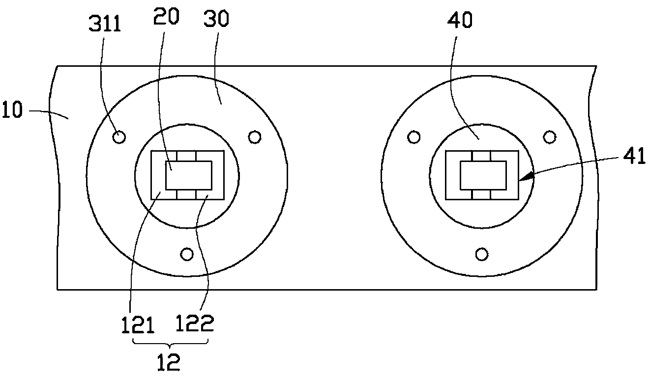
[0015] See figure 1 and figure 2 , an LED module 100 provided by an embodiment of the present invention includes a circuit board 10 , LEDs 20 mounted on the circuit board 10 , and a lens 30 covering each LED 20 .

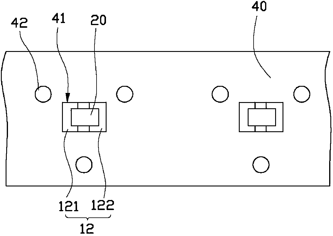
[0016] The circuit board 10 is used to carry the LED 20 and fix the lens 30 , and electrically connect the LED 20 to an external power source to provide power for the LED 20 . Please also see figure 2 , the circuit board 10 is roughly strip-shaped, and the circuit board 10 includes an insulating substrate and a circuit layer 12 formed on the substrate for electrically connecting the LEDs 20 to the circuit board 10 . The circuit layer 12 includes a plurality of first circuits 121 and second circuits 122, two adjacent first circuits 121 and second circuits 122 are spaced apart from each other, and each LED 20 is connected to two adjacent first circuits 121 and second circuits. circuit 122.

[0017] Please also see image 3 , the circuit board 10 is further prov...


PUM


Abstract

An LED module for use in a direct-type backlight module includes a printed circuit board, an LED arrange on the printed circuit board and electrically connected to the printed circuit board, and a lens covering the LED and fixed on the printed circuit board. A reflective layer is arranged on the printed circuit board. A semi-transparent surface is recessed and tampered from a top of a column-shaped protrusion at a center of the lens towards the LED. Part of light beams emitted from a center of the LED is refracted and diffused by the semi-transparent surface to an outside, and another part of the light beams emitted from a center of the LED is reflected by the semi-transparent surface to the reflective layer, and then reflected by the reflective layer to the outside.

Description

technical field [0001] The invention relates to a semiconductor structure, in particular to a light emitting diode module. Background technique [0002] Compared with traditional light sources, light emitting diodes (Light Emitting Diode, LED) have the advantages of light weight, small size, low pollution, long life, etc. As a new type of light source, it has been increasingly used in In various fields, such as street lights, traffic lights, signal lights, spotlights and decorative lights. [0003] Existing LED modules such as LED light bars generally include a circuit board and a plurality of LEDs mounted on the circuit board. The light emitting angle of the existing light emitting diodes is generally 120°, so in order to make the emitted light of the light bar uniform, a certain number of light emitting diodes must be installed in the light bar, and the interval between each adjacent two light emitting diodes should not be greater than the predetermined The numerical val...

Claims


Application Information

Patent Timeline
Patent Type & Authority Applications(China)
IPC IPC(8): H01L25/13H01L33/60H01L33/58
CPCF21V13/04F21K9/50G02F1/133603G02F1/133605G02F1/133606G02F1/133607
Inventor 张超雄黄哲瑄林厚德陈滨全
Owner ZHANJING TECH SHENZHEN
Why Eureka
Try Eureka