On-board charging unit and automatic charging method applying the same

A vehicle-mounted charging and charging plug-in technology, applied in the automotive field, can solve the problems of complex structure, high production cost, low charging efficiency, etc., and achieve the effect of convenient use and low cost

Active Publication Date: 2014-10-29
ZHEJIANG GEELY AUTOMOBILE RES INST CO LTD +1
View PDF5 Cites 23 Cited by
  • Summary
  • Abstract
  • Description
  • Claims
  • Application Information

AI Technical Summary

Problems solved by technology

According to relevant surveys, people's daily driving mileage is about 60km, which means that charging once cannot meet the driving needs of two days, and the vehicle needs to be charged every day.
However, it is extremely inconvenient to charge manually every day, and there will be problems of forgetting to charge and affecting the itinerary
[0003] Wireless charging is considered to be the development direction of electric vehicle charging technology in the future, but wireless charging is still in the experimental stage, and there are still many technical problems to be solved. Charging efficiency, if the concentricity of the two is not enough, it will greatly reduce the charging efficiency, and to achieve a perfect match will put forward high requirements on the driving level of the car owner, and there is a certain degree of difficulty in operation
[0004] Patent CN 103425073A provides an automatic retractable control system for charging plugs. However, it is applied to charging piles. Although it can achieve the purpose of automatic charging, it has a complex structure and high production costs, and can only be used for charging piles, so that electric vehicles Charging has some inflexibility

Method used


Image

  • On-board charging unit and automatic charging method applying the same
  • On-board charging unit and automatic charging method applying the same
  • On-board charging unit and automatic charging method applying the same

Examples


Embodiment Construction

[0029] In order to further explain the technical means and effects of the present invention to achieve the intended purpose of the invention, the specific implementation, structure, features and effects of the present invention will be described in detail below in conjunction with the accompanying drawings and preferred embodiments.

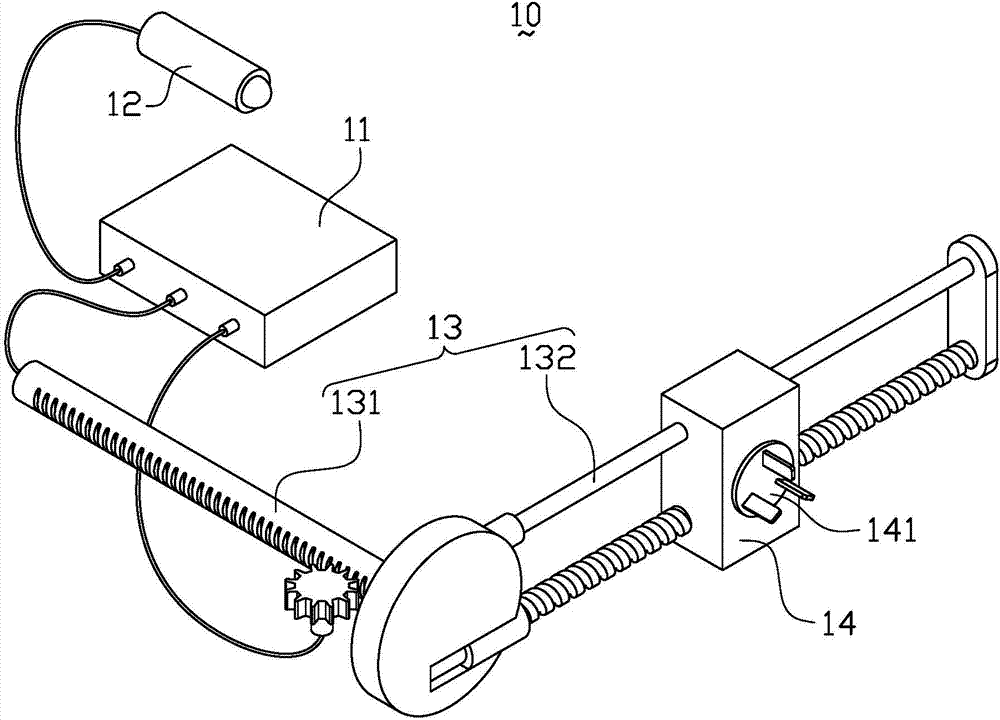
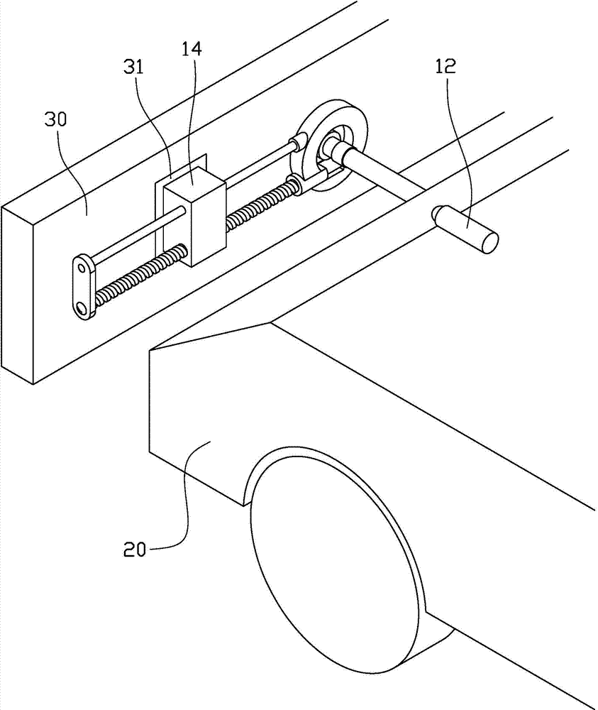
[0030] figure 1 It is a schematic diagram of the overall structure of the on-board charging device in one embodiment of the present invention. figure 2 It is a schematic diagram of the working state of the on-board charging device in one embodiment of the present invention. Such as figure 1 and figure 2 As shown, the vehicle charging device 10 of the present invention includes a controller 11, a position detection device 12, a mechanical arm 13, a charging mechanism 14 and an energy diagnosis system (not shown).

[0031] Wherein, the controller 11 is respectively connected with the signal of the position detection device 12, the mechanical a...


PUM


Abstract

Disclosed is an on-board charging unit. The on-board charging unit comprises a controller, a position detector, a mechanical arm and a charging mechanism, wherein the controller is connected the position detector, the mechanical arm and the charging mechanism through signals respectively, the position detector is used for collecting charging jacks around a vehicle body and position information of the mechanical arm and the charging mechanism, the mechanical arm is connected with the vehicle body, the charging mechanism is slidingly arranged on the mechanical arm, the front end of the charging mechanism is provided with a charging plug, and the controller controls the charging mechanism to slide on the mechanical arm to a position enabling the charging plug to correspond to the charging jacks and controls the mechanical arm to drive the mechanism to plug the charging plug into the charging jacks. The on-board charging unit can automatically determine the position of the charging jacks through the cooperation of the controller, the position detector and the mechanism arm, can automatically extend the mechanical arm to connect the jacks for charging and automatically retract the mechanical arm after charging, integrates existing mature industrial technologies and is low in costs and convenient to use.

Description

technical field [0001] The invention relates to automobile technology, in particular to a vehicle charging device and an automatic charging method using the device. Background technique [0002] Due to the limitation of the energy density of the current power battery, the cruising range of the current pure electric vehicle is only about 100km. According to relevant surveys, people's driving mileage is about 60km a day, which means that charging once can not meet the driving needs of two days, and the vehicle needs to be charged every day. However, manual charging every day is extremely inconvenient, and there may be problems of forgetting to charge and affecting the itinerary. [0003] Wireless charging is considered to be the development direction of electric vehicle charging technology in the future, but wireless charging is still in the experimental stage, and there are still many technical problems to be solved. Charging efficiency, if the concentricity of the two is n...

Claims


Application Information

Patent Timeline
Patent Type & Authority Applications(China)
IPC IPC(8): H02J7/00H01M10/44
CPCY02E60/10
Inventor 王之风王冰乐志国吴成明冯擎峰
Owner ZHEJIANG GEELY AUTOMOBILE RES INST CO LTD
Why Eureka
Try Eureka