
Hydraulic ejector

A technology of hydraulic injectors and nozzles, which is applied in the direction of jet pumps, machines/engines, steam/steam condensers, etc., and can solve problems such as damage to parts at the bottom of the injector, difficulty in controlling the spray water flow, and large impact force of the injector, etc., to achieve The effect of prolonging the service life, facilitating large-scale promotion and use, and improving work efficiency

Inactive Publication Date: 2014-11-05
孙婉琦
View PDF6 Cites 0 Cited by
  • Summary
  • Abstract
  • Description
  • Claims
  • Application Information

AI Technical Summary

Problems solved by technology

However, most of the hydraulic injectors currently on the market have the following problems: 1) The overall structure is complex and the cost is high; 2) The impact of the water flow inside the injector on the injector is relatively large, resulting in damage to the bottom parts of the injector; 3) Internal pressure Unstable, and the water spray flow is not easy to control; therefore, a new technical solution is urgently needed to solve the above technical problems

Method used


Image

  • Hydraulic ejector

Examples


Embodiment 1

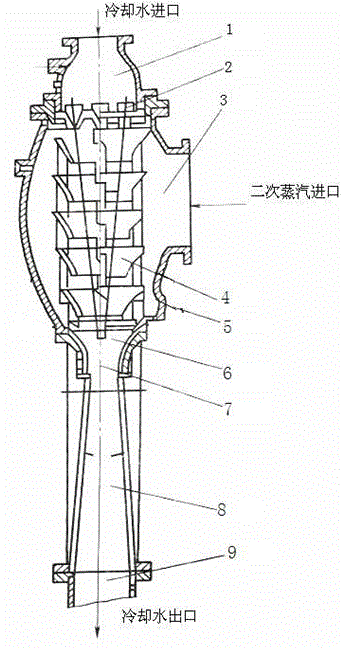
[0015] see figure 1 , a water power injector, which includes: the water power injector includes a body 5, a nozzle 2, a suction chamber 3, a mixing chamber 6 and a diffusion chamber 8 arranged on the body, the nozzle 2 is sequentially provided with suction Air chamber 3, mixing chamber 6 and diffusion chamber 8, the suction chamber is provided with a conical guide baffle. In this technical solution, a conical guide baffle is ingeniously arranged in the suction chamber, which plays a role in buffering and distributing the high-speed water flow. Due to the limited internal space of the injector, the conical guide baffle involved in this technical solution not only It only solves the impact problem of the water flow on the injector in the prior art, improves the working efficiency and prolongs the service life of the injector.

Embodiment 2

[0017] see figure 1 , as an improvement of the present invention, the hydraulic injector further includes a throat 7 , and the throat 7 is arranged between the mixing chamber 6 and the diffusion chamber 8 . The throat pipe is connected with the water flow coming down from the baffle plate to further ensure the guidance of the water flow and ensure that the water flow can reach the outlet of the cooling water quickly and accurately. All the other structures and advantages are identical to Embodiment 1.

Embodiment 3

[0019] see figure 1 , as a kind of improvement of the present invention, the diameter of described nozzle 2 is 15-20mm, proves through many experiments, the size of nozzle diameter plays a key role to pumping effect, and the diameter of nozzle is preferably 16-18mm, Further ensure the pumping effect. All the other structures and advantages are identical to Embodiment 1.


PUM


Abstract

The invention relates to a hydraulic ejector. The hydraulic ejector comprises a body, a nozzle (2), an air suction chamber (3), a mixing chamber (6) and a diffusion chamber (8), wherein the nozzle (2), the air suction chamber (3), the mixing chamber (6) and the diffusion chamber (8) are formed in the body, and the air suction chamber (3), the mixing chamber (6) and the diffusion chamber (8) are sequentially formed under the nozzle (2). The air suction chamber is provided with a conical guide baffle. According to the technical scheme, the conical guide baffle is arranged and can buffer and distribute high-speed water flow. Due to the fact that the internal space of the ejector is limited, the conical guide baffle solves the problem of impact on the ejector from the water flow, improves the work efficiency and prolongs the service life of the ejector.

Description

technical field [0001] The invention relates to an injector, in particular to a water power injector. Background technique [0002] The hydraulic ejector is a mechanical device with three effective functions of vacuuming, condensation and drainage. It uses a certain pressure of water to flow through nozzles that are symmetrically arranged to form a certain inclination to spray out and gather at one focus. Due to the high speed of the jet water flow, a negative pressure is formed around the chamber to create a vacuum in the chamber. In addition, due to the direct contact between the secondary steam and the jet water flow for heat exchange, most of the steam condenses into water, and a small amount of uncondensed steam and non-condensed steam The condensed gas is also rubbed against the high-speed sprayed water flow, mixed and squeezed, and is discharged through the diffuser tube, so that a higher vacuum is formed in the chamber. Hydraulic ejectors are widely used, mainly us...

Claims


Application Information

Patent Timeline
Patent Type & Authority Applications(China)
IPC IPC(8): F04F5/04F28B3/06
Inventor 孙婉琦
Owner 孙婉琦
Learn More