Electric linear movement device

A linear motion and electric technology, applied in the direction of electromechanical devices, transmission devices, electric components, etc., can solve the problems of small lead, difficult to meet the needs of high-precision linear motion, unstable optical mirror frame system, etc., to improve motion accuracy , avoid damage to the motor, and avoid the effect of large partial load

Inactive Publication Date: 2014-11-05
CENT SOUTH UNIV
View PDF7 Cites 2 Cited by
  • Summary
  • Abstract
  • Description
  • Claims
  • Application Information

AI Technical Summary

Problems solved by technology

[0003] Optical frames or linear motion mechanisms usually have larger loads, combined with figure 1 , if the load is too large, a larger motor power with a screw is required, and the optical frame or linear motion mechanism usually requires a linear motion device with a small structure. unstable
[0004] Furthermore, the lead of the screw-nut pair composed of the screw of the motor and the nut of the moving flange cannot be made very small, so it is difficult to meet the requirements of high-precision linear motion

Method used


Image

  • Electric linear movement device
  • Electric linear movement device
  • Electric linear movement device

Examples


Embodiment Construction

[0045] Embodiments of the present invention will be further described in detail below in conjunction with the accompanying drawings and examples. The following examples are used to illustrate the present invention, but should not be used to limit the scope of the present invention.

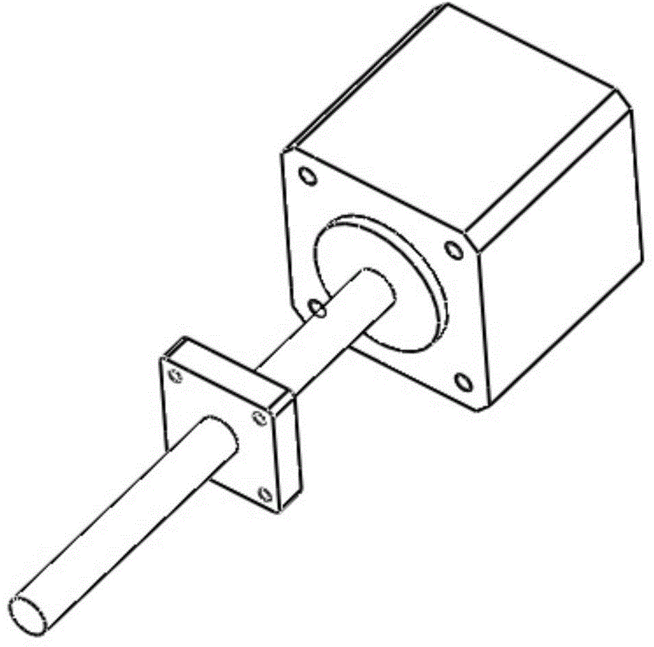
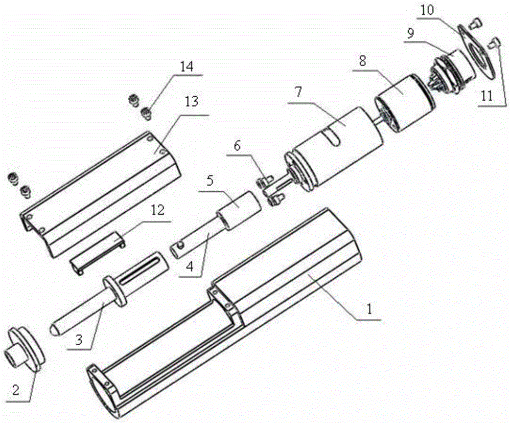
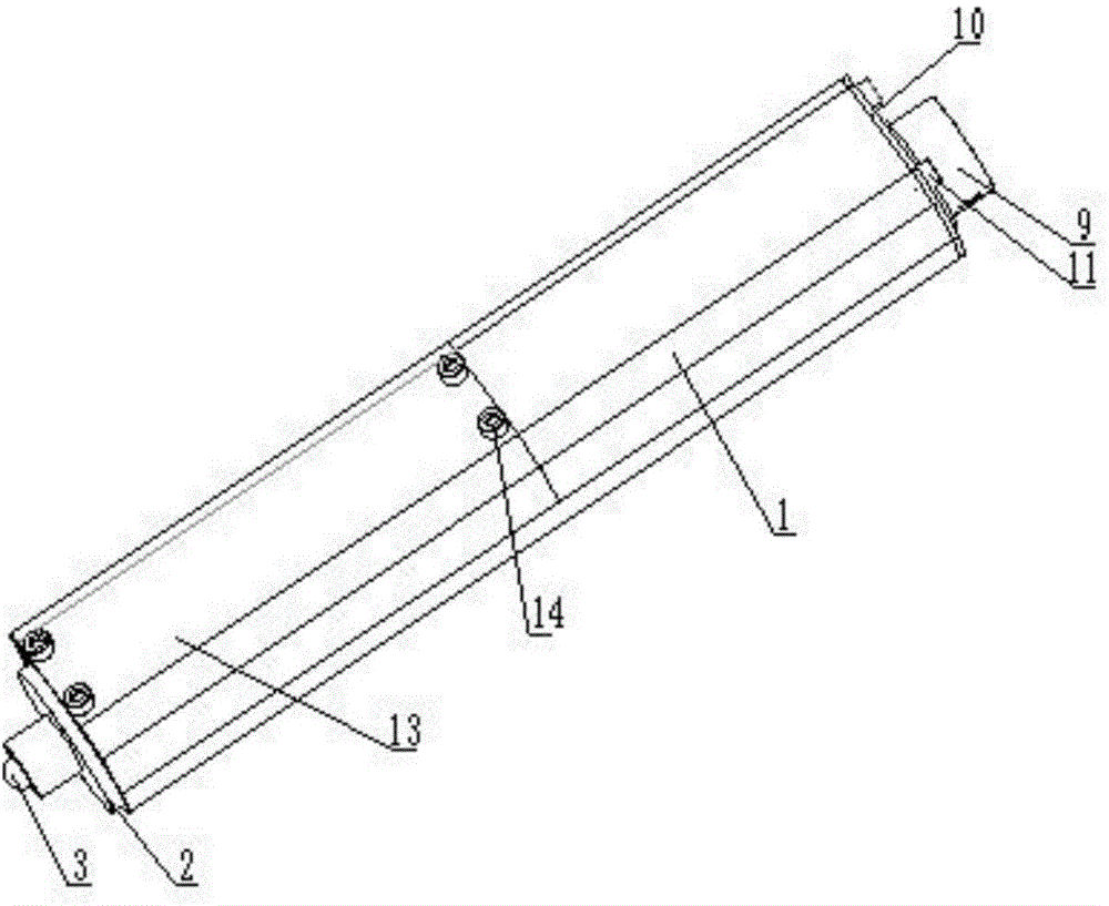
[0046] Such as figure 2 As shown, this embodiment provides an electric linear motion device, including a motor 8, a screw, and a nut 2. The electric linear motion device is provided with a reduction box 7 between the motor 8 and the screw.

[0047] The reduction box 7 is connected to the screw rod through the reversing assembly, and the screw rod cooperates with the nut 2 to form a screw nut pair;

[0048] The reversing assembly transmits torque to ensure that the motor 8 drives the screw to rotate after passing through the reduction box 7; and the reversing assembly ensures that the screw is axially and linearly fed under the side effect of the screw nut;

[0049] The electric linear motion de...


PUM


Abstract

The invention relates to an electric linear movement device. Due to the fact that a reduction box (7) is additionally arranged between a motor (8) and a screw, an integral structure of the device is not enlarged on the premise that the device has large driving force, problems of large unbalance loading and unstable system caused by the large structure are avoided, and movement precision of the device is improved. Further, the reduction box (7) is connected with the screw through a reversing assembly. Specifically, the reduction box (7) is connected with a cross connection rod (4) and an actuating rod (3) provided with a groove, so that the actuating rod (3) moves axially relative to the cross connection rod (4), adverse consequences caused by installation disalignment of the actuating rod (3) and the cross connection rod (4) are avoided, and the actuating rod (3) and the cross connection rod (4) have a function of overload protection when torque transferred by the motor (8) is too large. The electric linear movement device can be widely applied to automatic optical mirror brackets and linear movement mechanisms in other technical fields.

Description

technical field [0001] The invention relates to a linear motion device, in particular to an electric linear motion device based on a reduction box. Background technique [0002] The existing linear motion device is composed of a motor with a screw and a motion flange. The motor driver and controller can form a linear motion system, which is widely used in automatic adjustment of optical mirror frames and linear motion. Such as figure 1 As shown, the existing linear motion device consists of a motor with a screw and a moving flange. The motor rotates and rotates, and the screw nut moves, and the moving flange converts the rotating motion into linear motion. The motion flange is connected with the optical frame or the moving part of the linear motion mechanism to realize linear motion. [0003] Optical frames or linear motion mechanisms usually have larger loads, combined with figure 1 , if the load is too large, a larger motor power with a screw is required, and the optica...

Claims


Application Information

Patent Timeline
Patent Type & Authority Applications(China)
IPC IPC(8): F16H25/24H02K7/10
CPCF16H25/24F16H2035/103H02K7/10
Inventor 郑煜周剑英段吉安王丽军李继攀吕文
Owner CENT SOUTH UNIV
Why Eureka
Try Eureka