Pohotonic crystal fiber grating pressure sensing method adopting bimodal reflectance spectrum of cross-polarized mode

A photonic crystal fiber, orthogonal polarization technology, applied in the direction of force measurement by measuring the change of optical properties of materials when they are stressed, can solve problems such as the inability to measure lateral stress

Inactive Publication Date: 2014-11-05
HARBIN NORMAL UNIVERSITY
View PDF4 Cites 13 Cited by
  • Summary
  • Abstract
  • Description
  • Claims
  • Application Information

AI Technical Summary

Problems solved by technology

[0004] The present invention is to solve the problem that the existing fiber grating sensor cannot measure the transverse stress, and the present invention provides a pressure sensing method using the photonic crystal fiber grating with the double-peak reflection spectrum of the orthogonal polarization mode

Method used


Image

  • Pohotonic crystal fiber grating pressure sensing method adopting bimodal reflectance spectrum of cross-polarized mode
  • Pohotonic crystal fiber grating pressure sensing method adopting bimodal reflectance spectrum of cross-polarized mode
  • Pohotonic crystal fiber grating pressure sensing method adopting bimodal reflectance spectrum of cross-polarized mode

Examples


specific Embodiment approach 1

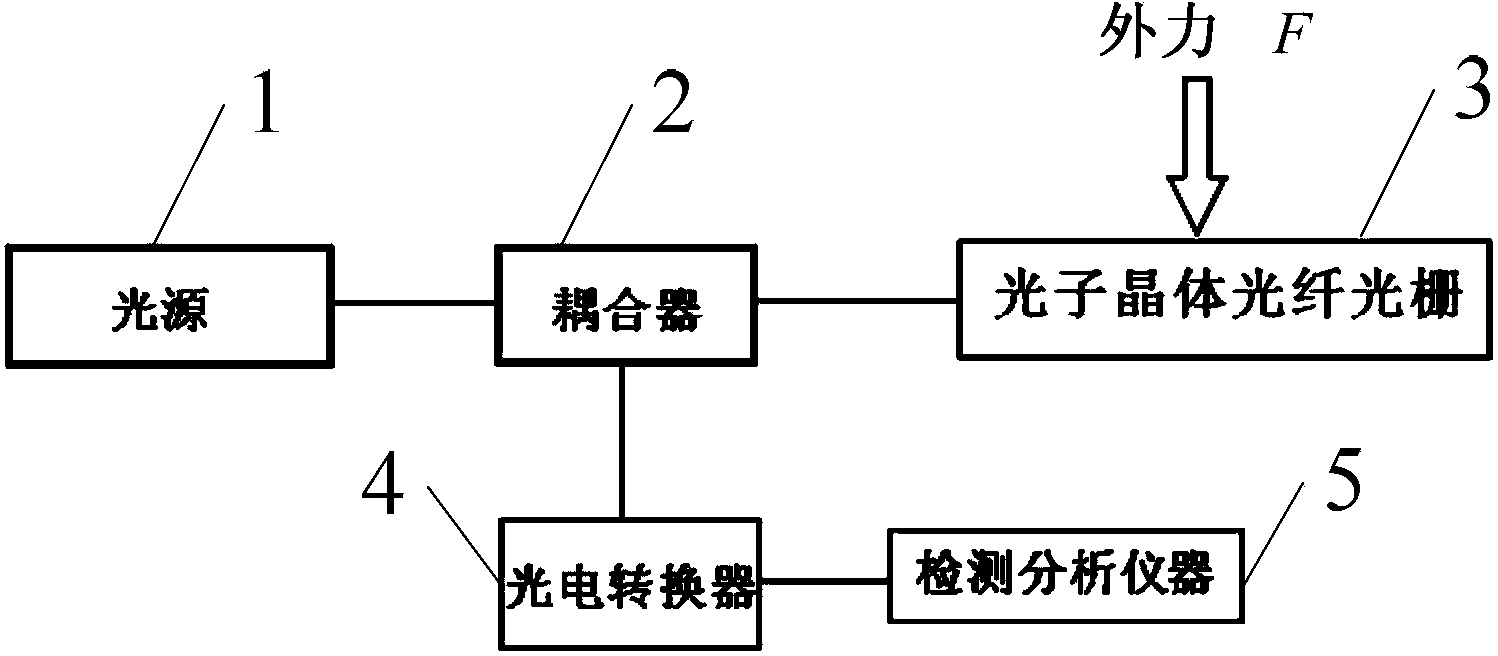
[0038] Specific implementation mode one: see figure 1 and 2 Describe this embodiment mode, a kind of pressure sensing method using the photonic crystal fiber grating of orthogonal polarization mode bimodal reflection spectrum described in this embodiment mode, the specific process of this method is:

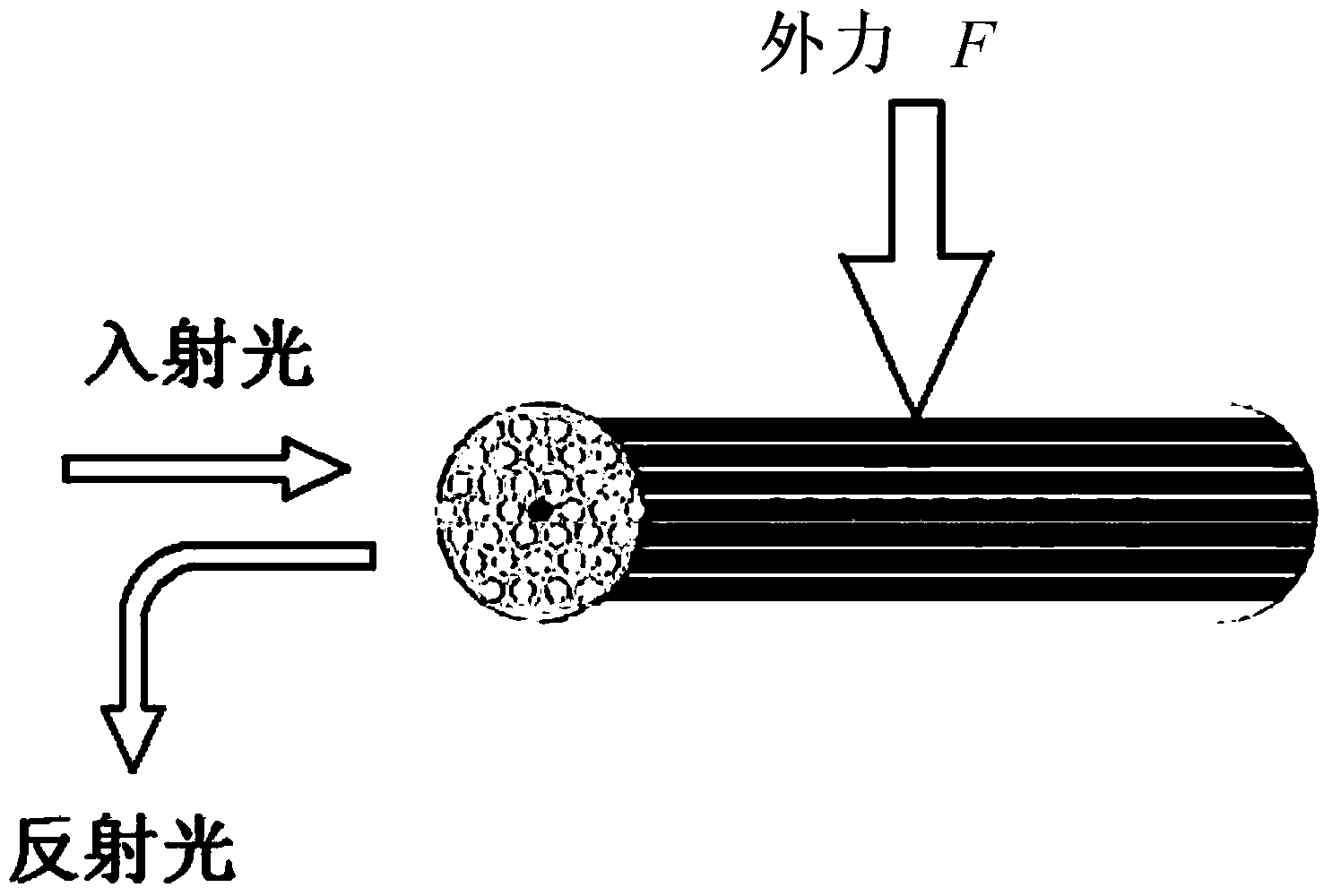
[0039] The light emitted by the light source 1 is coupled by the coupler 2 and then incident on the photonic crystal fiber grating 3 to which the external force F perpendicular to the photonic crystal fiber grating 3 has been applied. The photonic crystal fiber grating 3 generates reflected light, which is coupled by the coupler 2 Sent to the photoelectric converter 4, the electrical signal output by the photoelectric converter 4 is sent to the detection and analysis instrument 5;

[0040] The specific process of detecting and analyzing instrument 5 to obtain the value of external force F is as follows:

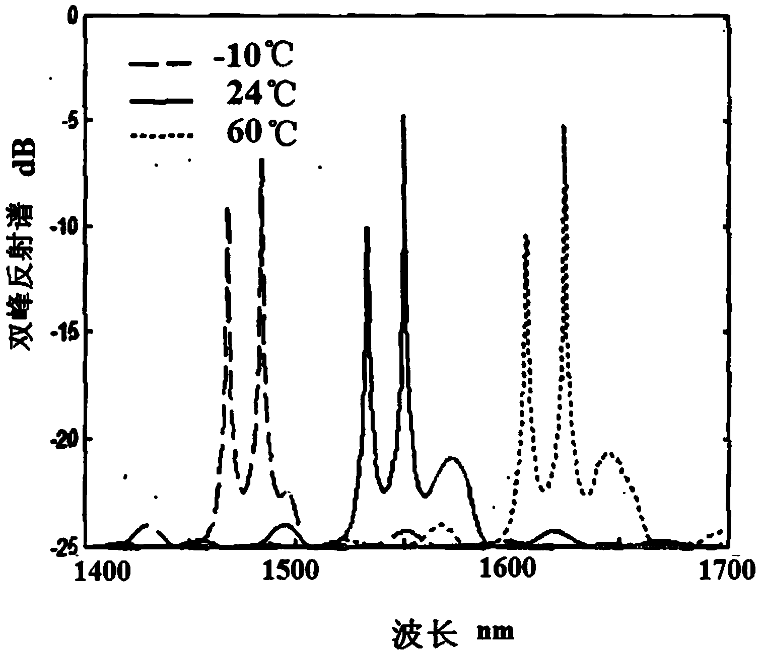
[0041] When an external force F perpendicular to the photonic crystal fi...

specific Embodiment approach 2

[0049] Specific embodiment 2: The difference between this embodiment and the pressure sensing method of a photonic crystal fiber grating using the bimodal reflection spectrum of the orthogonal polarization mode described in the specific embodiment 1 is that the K x (ε) and K y The calculation process of (ε) is,

[0050] When the photonic crystal fiber grating 3 is subjected to an external force F, the wavelength change of reflected light as follows,

[0051] d λ b λ b = dn co n co - n cl - dn cl n co - n ...

specific Embodiment approach 3

[0063] Specific embodiment three: The difference between this embodiment and the pressure sensing method of a photonic crystal fiber grating using the orthogonal polarization mode bimodal reflection spectrum described in the specific embodiment one is that the light emitted by the light source 1 is Broad spectrum natural light.


PUM


Abstract

The invention discloses a pohotonic crystal fiber grating pressure sensing method adopting the bimodal reflectance spectrum of a cross-polarized mode, and belongs to the field of pohotonic crystal fiber grating sensing. The method solves the problem that transversal stress can not be measured through an existing fiber grating sensing method. Light emitted by a light source is coupled by a coupler and then enters a pohotonic crystal fiber grating stressed with external force F perpendicular to the pohotonic crystal fiber grating. The pohotonic crystal fiber grating generates reflected light and is a polarization-dependent grating; the spectrum difference of the reflected light appears in the cross-polarization direction, and namely a reflectance spectrum bimodal curve appears. When the pohotonic crystal fiber grating is stressed with transverse pressure, the polarization property difference of a cladding material appears in the stress direction and the direction perpendicular to the stress direction due to the internal stress of the cladding material, the light reflectance spectrum bimodal curve moves, the bimodal distance changes at the same time, and the reflected light is converted into electrical signals through a photoelectric converter. A detection analyzer works out the pressure sensing quantity value through conversion according to sensing signals. The method is mainly applied to the pressure sensing field.

Description

technical field [0001] The invention belongs to the field of photonic crystal fiber grating sensing. Background technique [0002] Photonic crystal fiber grating sensing technology is a relatively advanced sensing technology at present. Photonic crystal fiber grating is based on the original fiber grating sensing principle, and realizes pressure sensing by using the characteristics of double-peak shift and interval change of reflection spectrum. Using this feature, a variety of optical fiber sensor devices with superior performance can be developed. Compared with ordinary fiber grating sensing principles, photonic crystal grating gratings have a wide range of reflection bandwidth, small additional loss, small size, and are easy to distinguish between temperature changes and pressure changes. , can be integrated with other optical devices, and is not affected by environmental dust and other excellent performances. [0003] When the temperature, stress, strain, or other physi...

Claims


Application Information

Patent Timeline
Patent Type & Authority Applications(China)
IPC IPC(8): G01L1/24
Inventor 励强华高社成孙江亭付淑芳
Owner HARBIN NORMAL UNIVERSITY
Why Eureka
Try Eureka