Novel method for manufacturing microprism type light reflecting material mold

A technology of reflective materials and production methods, applied in optics, optical components, instruments, etc., can solve the problems of difficult to meet the reflected light intensity, strict processing equipment and processes, difficult adjustment and replacement, etc., to achieve excellent wide-angle performance, processing method Simple, easy-to-process effects

Active Publication Date: 2014-11-05
ZHEJIANG DAOMING OPTOELECTRONICS TECH
View PDF5 Cites 4 Cited by
  • Summary
  • Abstract
  • Description
  • Claims
  • Application Information

AI Technical Summary

Problems solved by technology

like figure 1 , figure 2 As shown, the microprism mold obtained by this method has the same three cutting surfaces c of the triangular pyramid, that is, the microprism mold only has a microprism reflective unit of one structure, and two adjacent triangular pyramids are perpendicular to The degrees of the angle C between the directions are the same, and the reflected light intensity of the resulting reflective material is difficult to meet the requirements of identification in a wide range of illumination and observation angles, and it is easy to form a traffic safety hazard; moreover, this reflective material It presents completely different reflected light intensities in different directions, which is not conducive to subsequent construction
Therefore, some people also thought of using two different tools to realize micro-prism reflective units with different structures, but it is extremely difficult to adjust and replace the two tools during processing, which puts forward very strict requirements on processing equipment and technology, and it has not been effective so far. implement

Method used


Image

  • Novel method for manufacturing microprism type light reflecting material mold
  • Novel method for manufacturing microprism type light reflecting material mold
  • Novel method for manufacturing microprism type light reflecting material mold

Examples


Embodiment 1

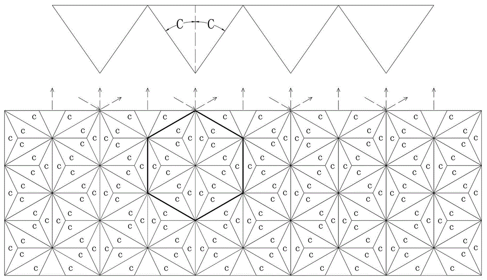
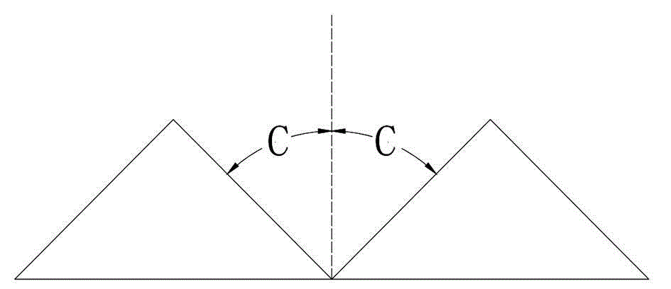
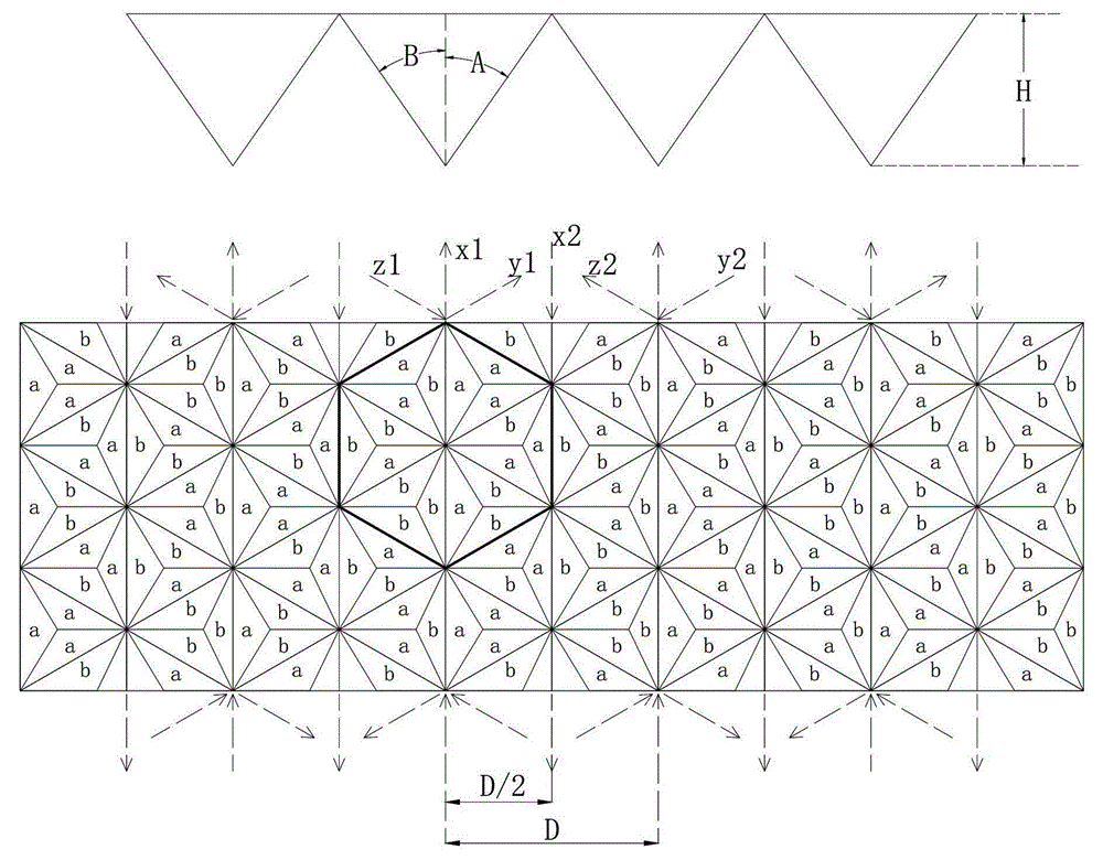
[0032] Such as Figure 3 to Figure 5 As shown, a novel manufacturing method of a microprism type reflective material mold includes the following steps:

[0033] (A) On a flat substrate, use a tool to cut the substrate in three directions, the angle between the three cutting directions is 60 degrees, the cutting line spacing D of the three cutting directions is 300μm~500μm, and the depth of cut H is 60 μm to 110 μm, the tool has two cutting angles A and B with different angles, the cutting angle A is 35.2 degrees to 35.4 degrees, and the cutting angle B is 35.1 degrees to 35.3 degrees;

[0034] (B) Offset the tool by a distance D / 2, and cut the substrate in the direction opposite to the three cutting directions in step (a), and form a microprism-type reflective material mold after cutting.

[0035] Specific, such as image 3 As shown, in the step (a), when cutting, first cut in the x1 direction, after the cutting is completed, the substrate is rotated 60 degrees, and the substrate is...


PUM


Abstract

The invention relates to a novel method for manufacturing a microprism type light reflecting material mold. A microprism mold obtained with an existing method only comprises microprism light reflecting units of one kind of structures, and the reflected light intensity of light reflecting materials obtained in this way can not meet the requirement that recognition is carried out within a wide illumination range and a wide observation angle range. The novel method mainly includes the following steps: a substrate is cut through a tool in three directions, wherein the distances between cutting lines in the three cutting directions range from 300 micrometers to 500 micrometers, and the tool has the cutting angle A and the cutting angle B which are different; the tool is displaced by the D/2 distance, the substrate is cut in the directions opposite to the three cutting directions, and the microprism type light reflecting material mold is formed after cutting. The microprism type light reflecting material mold obtained with the novel method has the excellent wide angle performance and is not obvious in the direction performance, and the requirement of recognition within the wide illuminating angle range and the wide observation angle range can be well met.

Description

technical field [0001] The invention relates to a manufacturing method of a microprism type reflective material mold, in particular to a manufacturing method of a novel microprism type reflective material mold. Background technique [0002] Reflective materials have the characteristics of reflecting incident light back to the light source, which has the advantages of energy saving and environmental protection, and are widely used in traffic safety signs, engineering signs, clothing and other fields. At present, reflective materials are mainly divided into two categories: glass bead reflective materials and microprism reflective materials. Among them, the microprism reflective material is formed by molding a microprism reflective material mold with a microprism reflective unit array structure on a polymer film material or pouring a polymer resin, and its core is a combination of triangular pyramids with a specific structure. The formed microprism reflective unit, the micropr...

Claims


Application Information

Patent Timeline
Patent Type & Authority Applications(China)
IPC IPC(8): G02B5/124B29C33/38
Inventor 王宏董云许德伟周金华郑魁
Owner ZHEJIANG DAOMING OPTOELECTRONICS TECH
Why Eureka
Try Eureka