Auto-focusing actuator driving structure

A focal actuator and drive structure technology, applied in the direction of instruments, installation, optics, etc., can solve the problems of complex assembly, failure to meet the requirements, and bulky coils, etc., and achieve the effect of easy assembly

Inactive Publication Date: 2014-11-05
SILITECH TECH CORP +1
View PDF6 Cites 9 Cited by
  • Summary
  • Abstract
  • Description
  • Claims
  • Application Information

AI Technical Summary

Problems solved by technology

[0002] Generally known auto-focus actuators, their auto-focus and anti-shake structures are all driven by a traditional coil with a permanent magnet to drive the lens or image sensor to achieve auto-focus or to compensate for the capture caused by vibration. The image is not clear, but the volume of the traditional coil is too large, and the assembly is more complicated. For electronic consumer products that are increasingly required to be light, thin and small, it is gradually unable to meet the demand.

Method used


Image

  • Auto-focusing actuator driving structure
  • Auto-focusing actuator driving structure
  • Auto-focusing actuator driving structure

Examples


no. 1 example

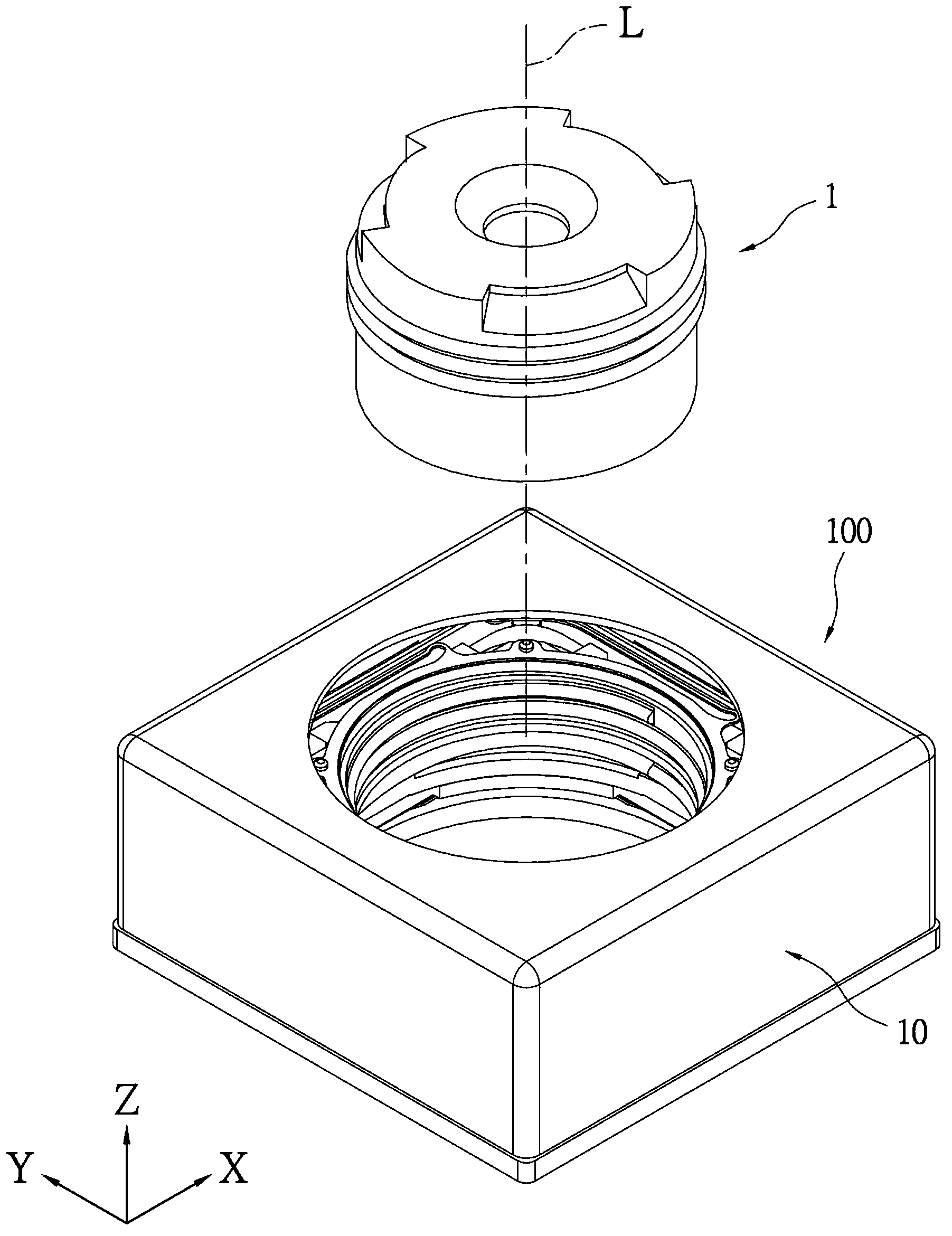
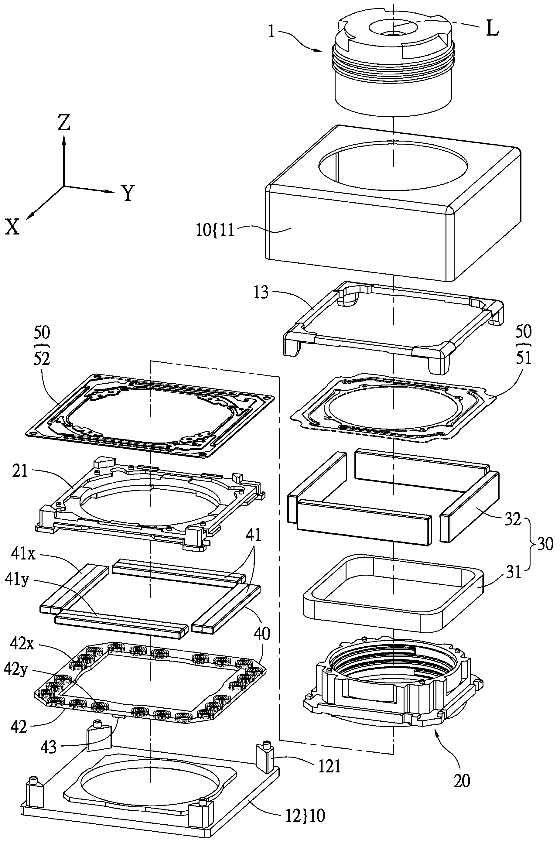
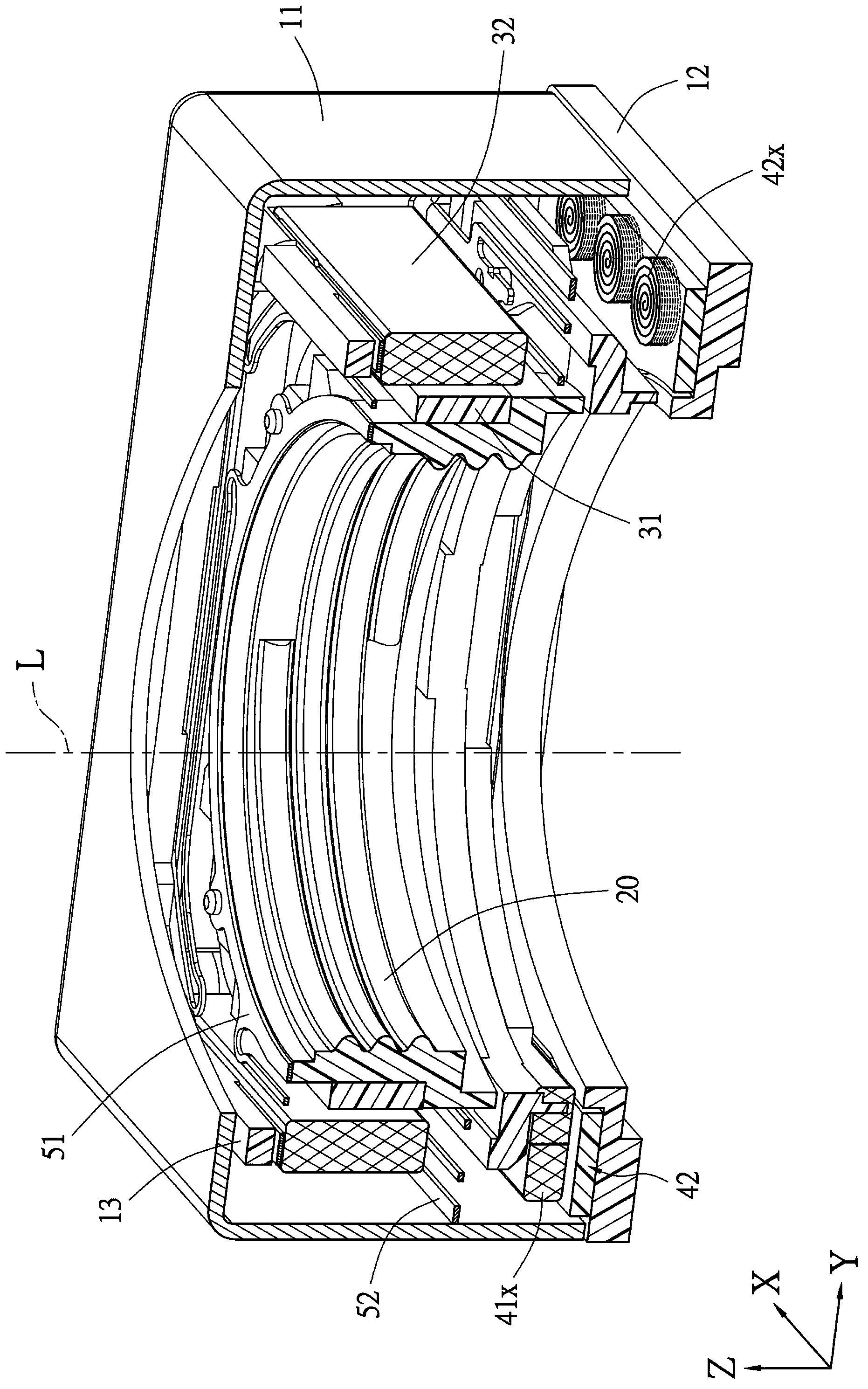
[0072] Please refer to figure 1 , the present embodiment provides an autofocus actuator driving structure 100 which can be mounted on a lens 1 . please refer again figure 2 and image 3 , the autofocus actuator driving structure 100 of this embodiment basically includes a body 10 , a lens barrel 20 , a carrier 21 , a first driving unit 30 and a second driving unit 40 .

[0073] The above-mentioned body 10 includes a frame body 11 and a base body 12 . Wherein, the frame body 11 is preferably made of metal material, the seat body 12 is preferably mainly made of plastic material, and the seat body 12 is assembled with the frame body 11 and located at the bottom of the main body 10 .

[0074] The above-mentioned lens barrel 20 is movably disposed inside the main body 10 . The lens barrel 20 is for the lens 1 to be mounted therein, and the lens 1 and the lens barrel 20 have the same optical axis L, the direction of the optical axis L can be defined as the Z-axis direction, and...

no. 2 example

[0082] Please refer to Figure 4 to Figure 6 In this embodiment, the autofocus actuator driving structure 200 basically includes a body 10', a lens barrel 20' and a driving unit 30'. The main difference between this embodiment and the above-mentioned embodiments is that the autofocus actuator driving structure 200 of this embodiment has only one driving unit 30 ′, and the driving unit 30 ′ includes a coil circuit board 31 ′ and a magnetic element group 32 '. The magnetic element group 31' is fixed on the outside of the lens barrel 20', the coil circuit board 32' is arranged inside the body 10' and surrounds the lens barrel 20' and the magnetic element group 32', and the coil circuit board 32' has several The printed coils 311x, 312x, 311y, 312y correspond to the positions of the magnetic element group 31'.

[0083] Specifically, the magnetic element group 31' includes at least two X-axis magnets 321x, 322x, and two Y-axis magnets 321y, 322y, and each X-axis magnet 321x, 322x...


PUM


Abstract

The invention relates to an auto-focusing actuator driving structure, which enables a lens to be assembled. The lens comprises an optical axis; the auto-focusing actuator driving structure comprises a body, a lens barrel and a driving unit; the lens barrel is movably arranged inside the body; the driving unit comprises a coin circuit board and a magnetic element group; the coin circuit board is provided with a plurality of printed coins; the plurality of printed coins are corresponding to positions of the magnetic element group to enable the lens barrel to move relative to the bottom part of the body with the help of the driving unit. A thin and small printed coin replaces the traditional huge coin, the auto-focusing actuator driving structure achieves the purposes of miniaturization and micromation and is convenient to be assembled; the plurality of printed coins can enable the control circuit or the control chip to precisely control the current value passing through each printed coin, the lens barrel or the carrier can precisely move relative to the bottom part of the body, precise focusing and position correction can be achieved, and thus the precise auto focusing and vibration compensation effects can be achieved.

Description

technical field [0001] The invention relates to an automatic focus actuator driving structure, in particular to a miniaturized and miniaturized automatic focus actuator driving structure. Background technique [0002] Generally known auto-focus actuators, their auto-focus and anti-shake structures, use traditional coils with permanent magnets to drive the lens or image sensor to achieve auto-focus or to compensate for the capture caused by vibration. The image is not clear, but the volume occupied by traditional coils is too large, and the assembly is relatively complicated. For electronic consumer products that are increasingly required to be light, thin, and small, they are gradually unable to meet the needs. [0003] Therefore, how to improve the above-mentioned problems by means of structural design has become an important issue to be solved by those skilled in the art. The present invention is to propose a reasonable design and effectively improve the above-mentioned p...

Claims


Application Information

Patent Timeline
Patent Type & Authority Applications(China)
IPC IPC(8): G02B7/09H02K33/18
Inventor 周进益张钧闵游腾健
Owner SILITECH TECH CORP
Why Eureka
Try Eureka