
Plasma antenna module and plasma processing device

A plasma antenna and module technology, applied in the direction of plasma, antenna support/mounting device, discharge tube, etc., can solve the problem of different processing speed

Active Publication Date: 2020-11-17
GIGALANE CO LTD
View PDF8 Cites 0 Cited by
  • Summary
  • Abstract
  • Description
  • Claims
  • Application Information

AI Technical Summary

Problems solved by technology

[0004] However, depending on the environmental conditions for processing the plasma, the density of the plasma changes, so there is a problem that the entire substrate is not processed at the same speed, but the processing speed is locally different. For example, a part of the substrate may be processed at a high speed. Another part of the problem being processed at a slow pace

Method used


Image

  • Plasma antenna module and plasma processing device
  • Plasma antenna module and plasma processing device
  • Plasma antenna module and plasma processing device

Examples


Embodiment Construction

[0037] Hereinafter, specific contents for implementing the present disclosure will be described in detail with reference to the drawings. However, in the following description, when it may unnecessarily obscure the gist of the present disclosure, a specific description of well-known functions or configurations will be omitted.

[0038] Before describing the embodiments of the present disclosure in detail, the upper side of the drawing may be referred to as "upper" or "upper side" of the configuration shown in the drawing, and the lower side thereof may be referred to as "below" or "lower side". In addition, the rest of the configuration shown in the drawings except between the upper and lower sides or the upper and lower parts may be referred to as “side” or “side”.

[0039] In the present disclosure as a whole, the left side of the drawing may be referred to as "left" or "left side" of the configuration shown in the drawing, and the right side thereof may be referred to as "r...


PUM


Abstract

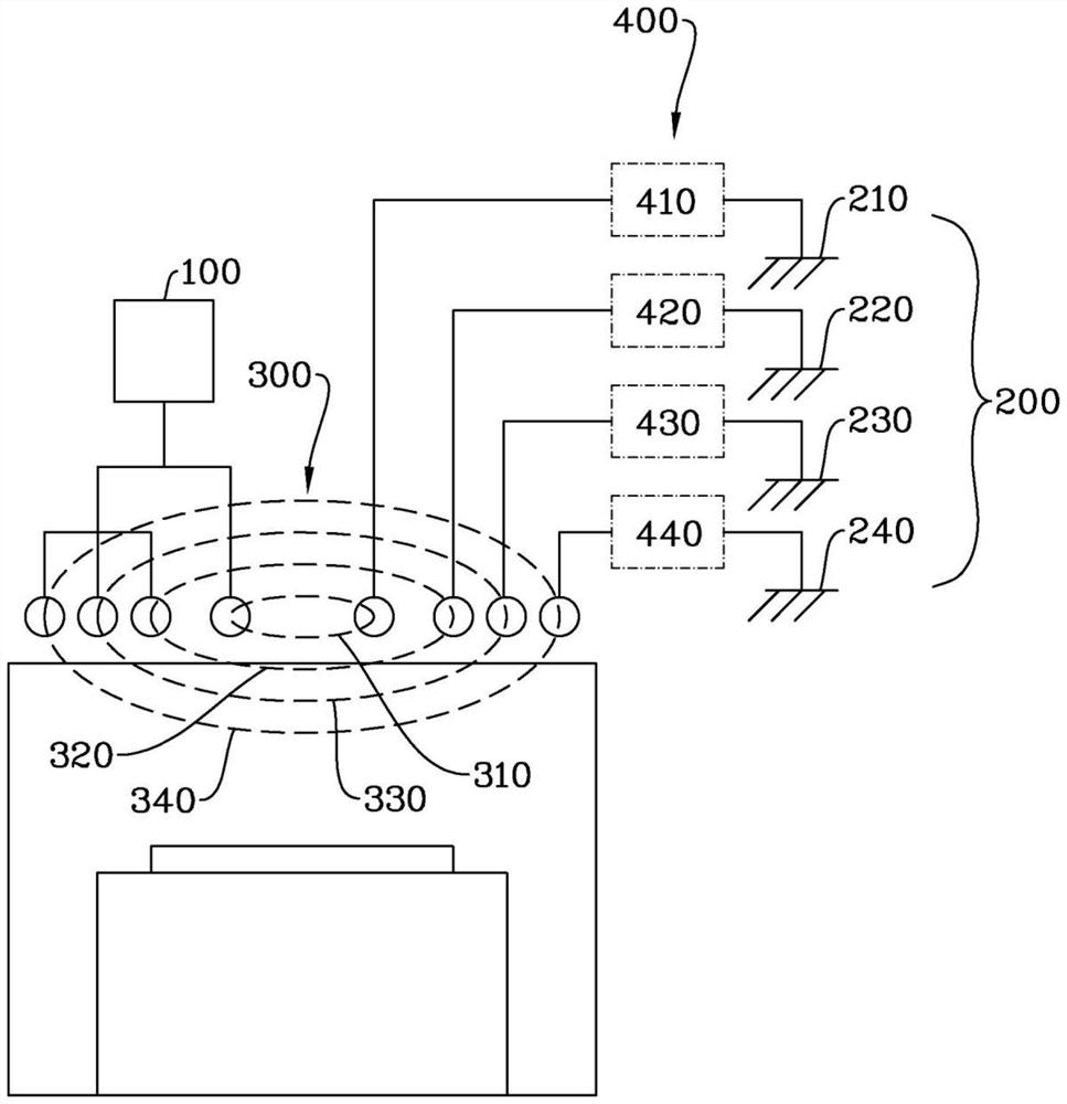
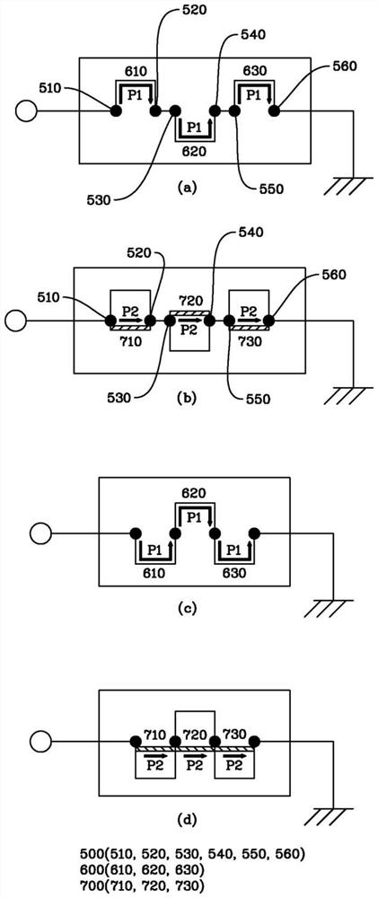
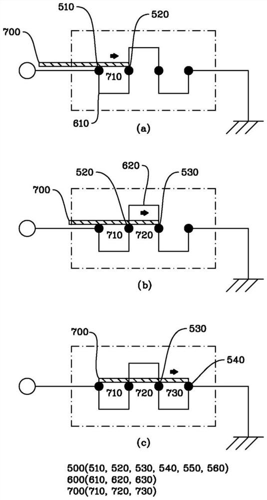
The invention relates to a plasma antenna module and a plasma processing device. The plasma antenna module according to an embodiment of the present disclosure comprises: a plasma antenna; the grounding part is electrically connected to one side of the plasma antenna; a power supply unit that supplies power to the other side of the plasma antenna; and a bypass part interposed between the plasma antenna and the power supply part or between the plasma antenna and the ground part. The detour portion includes a plurality of contacts connected to each other on the first path. When two or more of the plurality of contacts are additionally connected to each other, the bypass portion forms a second path different from the first path. The bypass unit controls a current value flowing into the plasmaantenna in accordance with the number of contacts included in the second path.

Description

technical field [0001] The present disclosure relates to a plasma antenna module, and in more detail, to a plasma antenna module for individually controlling current flowing into each plasma antenna. Background technique [0002] Plasma processing devices generally include an inductively coupled plasma source (Inductively Coupled Plasma Source, ICP) type and a capacitively coupled plasma source (Capacitively Coupled Plasma Source, CCP) type, and new ones capable of producing higher plasma densities are also used The plasma source type is coil wave plasma and ECR (Electron cyclotron resonance plasma, Electron cyclotron resonance plasma) plasma source type, etc. [0003] The plasma processing apparatus can form a process gas into plasma by supplying power to the plasma antenna, and can process a substrate (for example, etching, vapor deposition, etc.) using the formed plasma. In this case, the density of the plasma may become one of the important factors for determining the p...

Claims


Application Information

Patent Timeline
Patent Type & Authority Applications(China)
IPC IPC(8): H01J37/32H05H1/24
CPCH01J37/32091H01J37/3211H01J37/32183H05H1/24H01Q1/26
Inventor 金亨源李允诚郑熙锡
Owner GIGALANE CO LTD
Learn More