Pulverized coal decoupling combustor and decoupling combustion method thereof

A combustion method and burner technology, which is applied in the direction of combustion method, burner, burner for burning powder fuel, etc., can solve the problem of unadjustable coal concentration separation performance, unsuitable for furnace structure, and difficult to realize decoupling large-scale combustion furnace To achieve the effects of stable combustion, suppressing the formation of NOx, increasing the temperature, and increasing the entrainment space

Inactive Publication Date: 2011-12-28
INST OF PROCESS ENG CHINESE ACAD OF SCI
View PDF12 Cites 15 Cited by
  • Summary
  • Abstract
  • Description
  • Claims
  • Application Information

AI Technical Summary

Problems solved by technology

However, these patents are only suitable for layered combustion technology, and only suitable for layered decoupling combustion furnaces below 100t / h, and it is difficult to realize large-scale decoupling combustion furnaces for pulverized coal combustion
[0008] The patent "Low NOx emission pulverized coal decoupling burner and pulverized coal decoupling combustion method" (China Invention Patent Application No.: 201110033811.8) invented a pulverized coal decoupling burner and pulverized coal decoupling combustion method, the coal Powder concentration and stable combustion are an integrated structure, and the dense and light nozzles are also arranged in a centralized manner. The separation performance of the pulverized coal concentration of this burner structure cannot be adjusted. In addition, the installation space of the boiler burner needs to have a fixed size space, which is not suitable for the dispersion of multiple nozzles. Arranged Furnace Structure

Method used


Image

  • Pulverized coal decoupling combustor and decoupling combustion method thereof
  • Pulverized coal decoupling combustor and decoupling combustion method thereof

Examples


Embodiment Construction

[0050] The pulverized coal decoupling burner and decoupling combustion method of the present invention will be further described below.

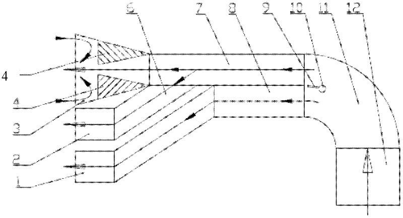
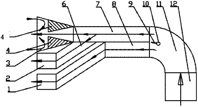
[0051] The pulverized coal decoupling burner provided by the invention, such as figure 1 As shown, it consists of a plurality of burner nozzles and an inertial separator connected to the burner nozzles through conduits; along the airflow direction from front to rear, there are inertial separators, conduits and burner nozzles in sequence.

[0052] The plurality of burner nozzles are respectively three-stage nozzles 1, two-stage nozzles 2 and one-stage nozzles 3; the three-stage nozzles 1 communicate with the inner side of the rear end of the inertial separator 11 through the light side airflow conduit 8; The secondary nozzle 2 communicates with the inside of the rich-side airflow conduit 7 through the secondary nozzle conduit 6 ; the primary nozzle 3 communicates with the outside of the rear end of the inertial separator 11 through the rich-s...


PUM


Abstract

The invention relates to a pulverized coal decoupling combustor and a decoupling combustion method thereof. The decoupling combustor comprises a first-stage air duct (12), an inertia separator (11), air current conduits and a spout which are sequentially connected along the air current direction, wherein the air current conduits comprise a dense side air current conduit (7) and a fresh side air current conduit (8); the fresh side air current conduit (8) is communicated with a third-stage spout (1); the dense side air current conduit (7) is connected with a first-stage spout (3); a second-stage spout conduit (6) communicated with the dense side air current conduit (7) is led out of a pipeline between the dense side air current conduit (7) and the first-stage spout (3) on the dense side aircurrent conduit (7); the second-stage spout conduit (6) is communicated with a second-stage spout (2); the first-stage spout (3) is a gradually-increasing spout; a pair of pulverized coal collecting flame stabilizing devices (4) is oppositely arranged at the upper side and the lower side inside the front end of the first-stage spout (3); the cross sections of the pulverized coal collecting flame stabilizing devices (4) along the air current direction is gradually increased; and the area of the cross section of an air current channel is decreased along the air current direction, thus the coupling combustion is realized.

Description

technical field [0001] The invention relates to the field of pulverized coal combustion equipment, in particular, the invention relates to a pulverized coal decoupling burner and a decoupling combustion method thereof. Background technique [0002] In the practical application of pulverized coal combustion, with the increase of the combustion temperature and oxygen concentration of the pulverized coal-air mixture in the combustion stage, the pulverized coal is more likely to be burned quickly and fully, and the fly ash combustibles (unburned carbon and CO ) content is reduced; at the same time, high temperature oxygen enrichment will make the NO produced in the combustion process x On the other hand, the lower the combustion temperature and oxygen concentration of the pulverized coal-air mixture in the combustion stage, the better the suppression of nitrogen oxides NO x Generated, but coal dust is less likely to burn out. Therefore, the removal of fly ash combustibles and ...

Claims


Application Information

Patent Timeline
Patent Type & Authority Applications(China)
IPC IPC(8): F23D1/00
Inventor 郝江平李静海高士秋何京东许光文
Owner INST OF PROCESS ENG CHINESE ACAD OF SCI
Why Eureka
Try Eureka