
RF power amplifier and electronic system

A technology of radio frequency power and electronic systems, applied in the direction of high-frequency amplifiers, etc., can solve the problems of .2 volts to 4.2 volts, affecting the output power accuracy of radio frequency power amplifiers, etc.

Active Publication Date: 2014-11-05
ADVANCED SEMICON ENG INC
View PDF2 Cites 6 Cited by
  • Summary
  • Abstract
  • Description
  • Claims
  • Application Information

AI Technical Summary

Problems solved by technology

Because the voltage value of the mobile phone battery will vary considerably, it may vary from 3.2 volts to 4.2 volts, thus affecting the accuracy of the output power of the RF power amplifier

Method used


Image

  • RF power amplifier and electronic system
  • RF power amplifier and electronic system
  • RF power amplifier and electronic system

Examples


Embodiment Construction

[0056]The terms first, second, third etc. may be used herein to describe various elements, but these elements should not be limited by these terms. These terms are used to distinguish one element from another. Thus, a first element discussed below could be termed a second element without departing from the teachings of the inventive concepts.

[0057] A 3G power amplifier (PA) module in the prior art adopts a two-chip design, one CMOS chip provides a reference voltage and reference current and a control circuit, and the other GaAs chip provides a power amplifier circuit.

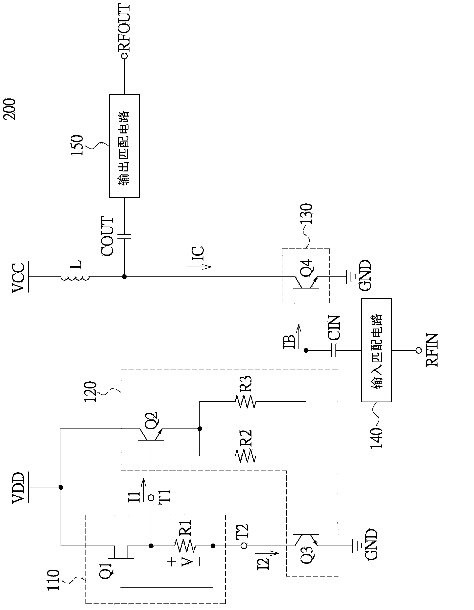
[0058] At least one embodiment of the present disclosure is designed using GaAs HBT+D-mode pHEMT process , The 3G PA module can be made into a single crystal, and the characteristics of this disclosure are that no reference voltage is required, and the circuit is simplified and the area is reduced.

[0059] [Example of RF Power Amplifier]

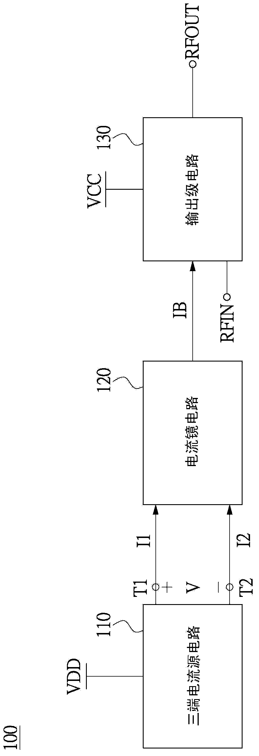
[0060] Please refer to figure 1 , figure 1 It is a schematic ...


PUM


Abstract

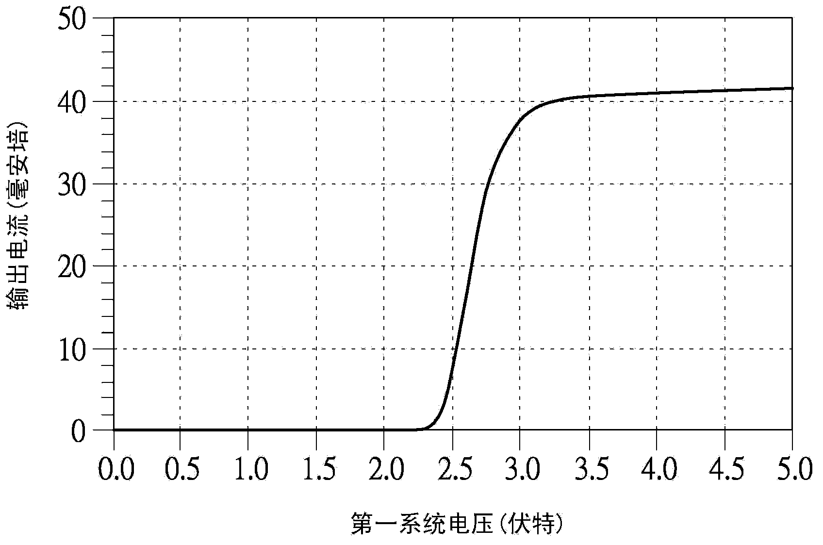
The present invention discloses an RF power amplifier which adopts a single chip design without reference voltage, and the RF power amplifier includes a three-terminal current source circuit, a current mirror circuit and an output stage circuit. The three-terminal current source circuit receives a first system voltage and outputs a first current and a second current based on the first system voltage, and a source voltage exists between a first output point of the first current and a second output point of the second current. The current mirror circuit receives the first current and the second current, and generates a bias current based on the first current and the second current. The output stage circuit receives the bias current to work at an operation bias point. The RF power amplifier enables the first system voltage to be between the first voltage and the second voltage through the source voltage of the three-terminal current source circuit, so that the output stage circuit outputs an output current which does not change along with the first system voltage, and which has temperature compensation.

Description

technical field [0001] The present invention relates to a radio frequency power amplifier, in particular to a radio frequency power amplifier using a three-terminal current source for bias. Background technique [0002] With the development of the Internet, people are accustomed to receiving large amounts of information quickly, especially after the advancement of wireless communication technology in recent years, personal mobile products, such as mobile phones, personal digital assistants and other products, have become popular at an astonishing speed. People want to be able to grasp real-time information, but also hope to have real-time online support. Therefore, the Wireless Local Area Network (WLAN) and the third generation (3G) / fourth generation (4G) network that combine the Internet and wireless communication are just a solution to meet people's needs. [0003] In wireless communication handheld devices, the main DC power consumption comes from the RF power amplifier....

Claims


Application Information

Patent Timeline
Patent Type & Authority Applications(China)
IPC IPC(8): H03F3/189
Inventor 丁兆明张欣晴
Owner ADVANCED SEMICON ENG INC
Learn More