

Lighting device
A lighting device and light-emitting diode technology, which is applied to lighting devices, fixed lighting devices, components of lighting devices, etc., can solve the problems that users cannot get high-quality sleep, fatigue is high, and people's fatigue is reduced.
- Summary
- Abstract
- Description
- Claims
- Application Information
AI Technical Summary
Problems solved by technology
Method used
Image

Examples
no. 1 approach
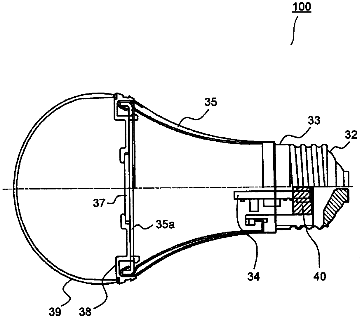
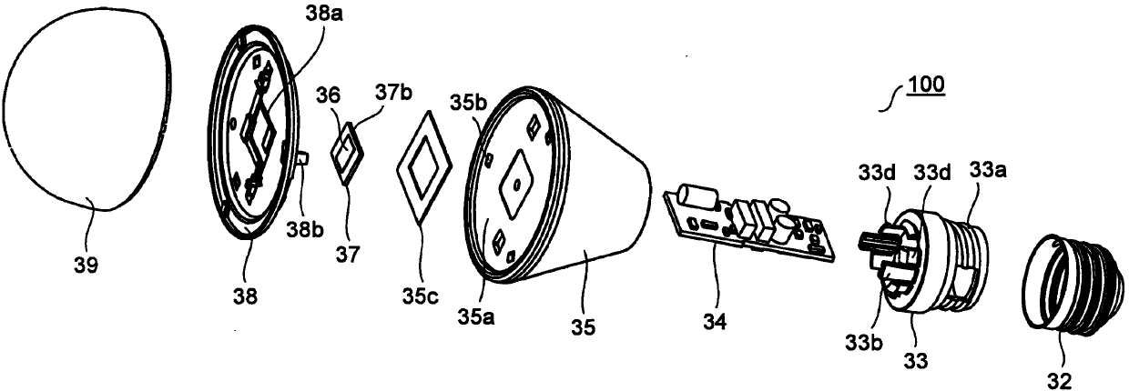
[0124] First, a lighting device according to a first embodiment of the present invention will be described. figure 1 , figure 2 A side sectional view and an exploded perspective view showing the lighting device according to the first embodiment. The lighting device 100 is a light bulb type attached to a lighting fixture, and has a base 32 at one end. An LED module 37 including an LED element 36 is arranged inside the lighting device 100 . The LED module 37 is formed so that the LED element 36 is mounted on the light source board|substrate 37b.
[0125] The appearance of the illuminating device 100 is formed by a lamp cap 32 , a support member 33 , a heat sink 35 and a transmission cover 39 . The lamp cap 32 is formed, for example, of the E26 type and is screwed to a lamp socket powered from the mains. The support member 33 is formed in a cylindrical shape from an insulator such as a resin molded product, and the screw portion 33 a is screwed to the inner surface of the ba...
no. 2 approach
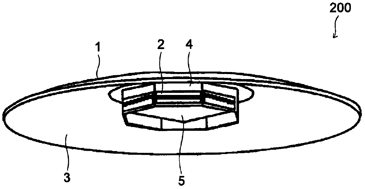
[0139] Next, a lighting device according to a second embodiment of the present invention will be described. image 3 It is an overall perspective view of the lighting device viewed from below. The lighting device 200 constitutes a ceiling light as a lighting fixture, and is installed on a ceiling surface of a room. The lighting device 200 may also be a lighting fixture installed on an indoor side wall.
[0140] The lighting device 200 includes a remote controller (not shown) and a circular and generally plate-shaped main body 1 for illuminating the indoor floor below, and the main body 1 is fixed on the indoor ceiling above. The main body 1 includes a light source substrate 2 , a reflection plate 3 , a frame 4 and an illumination control unit 5 .
[0141] The light source substrate 2 is formed in a rectangular shape in plan view, and is mounted on the lower surface of the main body 1 through the frame 4 in an upright state perpendicular to or substantially perpendicular to t...
no. 3 approach
[0173] Next, a lighting device according to a third embodiment of the present invention will be described. In addition, since the basic structure of this embodiment is the same as that of the above-mentioned second embodiment, the same components as those of the second embodiment are given the same reference numerals as above, and descriptions and descriptions of the drawings are omitted.
[0174] In the lighting device 200 of the third embodiment, Figure 5 The illustrated CPU 11 executes a program in accordance with an operation signal input from the input unit 15 to determine the timing of lighting. For example, the timing of lighting can be determined by pressing a switch not shown. In addition, the timing of lighting may be determined when the preset time is reached by a timer not shown in the figure or when the elapse of the preset time is detected.
[0175] When lighting is commanded, the CPU 11 issues a command to the PWM control circuit 13 so that the white LED elem...
PUM
 Abstract
Description
Claims
Application Information