
Sweeping robots and floor handling units

A technology for cleaning robots and robots, applied in cleaning devices, robot cleaning machines, vacuum cleaners, etc., can solve the problems of affecting cleaning, unsealed dust suction ports, poor dust suction effect, etc., and achieve the effect of simple structure and improved cleaning efficiency.

Active Publication Date: 2017-07-04
ECOVACS ROBOTICS (SUZHOU ) CO LTD
View PDF6 Cites 4 Cited by
  • Summary
  • Abstract
  • Description
  • Claims
  • Application Information

AI Technical Summary

Problems solved by technology

[0003] If the walking direction is set to the front, the existing cleaning robots on the market are generally only equipped with sealing strips at the rear and both sides of the dust suction port. The disadvantage of this structure is that the front of the dust suction port is not sealed, which greatly reduces If the vacuum degree of the vacuum cleaner is reduced, some difficult-to-remove dust will accumulate in the dust suction port and the dust suction channel, and the dust suction effect will be poor.
However, if a sealing strip is installed on the front of the cleaning robot's suction port, the sealing strip will prevent dust or debris from reaching the suction port during the cleaning process, affecting further cleaning.

Method used


Image

  • Sweeping robots and floor handling units
  • Sweeping robots and floor handling units
  • Sweeping robots and floor handling units

Examples


Embodiment 1

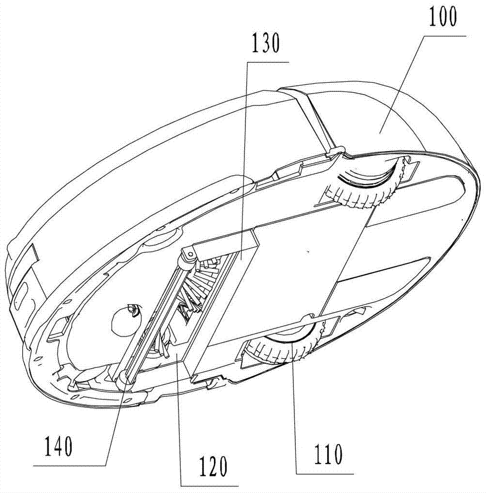
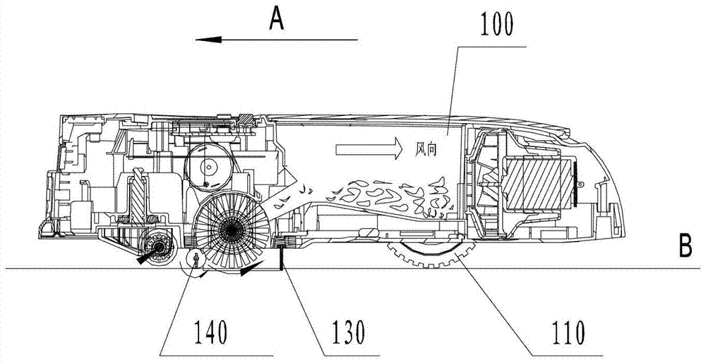
[0025] figure 1 It is a schematic structural diagram of a cleaning robot according to an embodiment of the present invention; figure 2 It is a schematic side view of a cleaning robot according to an embodiment of the present invention. Such as figure 1 and combine figure 2 As shown, the present invention provides a cleaning robot, which includes a robot body 100 with a driving wheel 110 on the body 100 and a dust suction port 120 at the bottom of the body 100 . If the walking direction A of the cleaning robot is set as the front, the rear and both sides of the dust suction port 120 are provided with a static sealing strip 130, and the lower edge of the static sealing strip 130 extends to the working surface to be cleaned; A dynamic seal 140 is also provided in front of 120 .

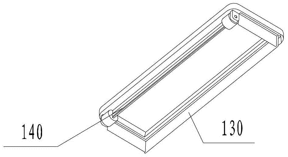
[0026] image 3 It is a schematic diagram of a local structure of the dust suction port according to the embodiment of the present invention, Figure 4 It is a schematic structural diagram of a d...

Embodiment 2

[0028] Figure 5 It is a schematic diagram of the swing angle position of the dynamic seal in Embodiment 2 of the present invention. control image 3 and combine Figure 5 As shown, the difference between this embodiment and Embodiment 1 is that in this implementation, the dynamic sealing strip 142 is a sealing sheet, and the sealing sheet is arranged at the front of the dust suction port 120, and its top and the bottom of the body 100 can be connected to each other. Rotationally connected, the sealing sheet is driven to swing by a driving motor. Specifically, the dynamic sealing strip 142 in the dynamic sealing member 140 can also be rotatably connected to the bottom of the body 100 through a pivot 143 . The actuator includes a pivot 143 and a driving motor (not shown in the figure) connected thereto. Driven by the driving motor, the dynamic sealing strip 142 rotates or swings around the pivot 143 . When the dynamic sealing strip 142 rotates around the pivot 143 , the rot...

Embodiment 3

[0030] Figure 6 It is a structural schematic diagram of the actuator of the third embodiment of the present invention. Such as Figure 6 As shown, the actuator can also be a lifting mechanism 200, the lifting mechanism 200 includes a sprocket 201 and a chain 202, the chain 202 is connected with the sprocket 201 and the dynamic sealing strip 142 respectively, and the sprocket 201 is also connected with the dynamic sealing strip 142 A driving motor (not shown in the figure) is connected, and driven by the driving motor, the lifting mechanism 200 drives the dynamic sealing strip 142 to translate up and down. The height of the dynamic sealing strip 142 moving up and down is less than or equal to the distance from the edge of the suction port to the working surface to be cleaned.

[0031] The dynamic sealing strip 142 in this embodiment can also be the sealing sheet in the second embodiment, but the difference from the second embodiment is that the sealing sheet can be arranged ...


PUM


Abstract

A cleaning robot comprising a robot machine body (100). Drive wheels (110) are arranged on the machine body (100). A dust intake opening (120) is provided at the bottom part of the machine body (100). With the direction in which the cleaning robot travels serving as the front (A), a static seal (130) is arranged at the rear and two sides of the dust intake opening (120). The lower edge of the static seal (130) extends towards a to-be-cleaned work surface (B). A dynamic sealing element (140) is arranged at the front of the dust intake opening (120). The dynamic sealing element (140) comprises an actuating element (141) and a dynamic seal (142). A gap between the dynamic seal (142) and either the edge of the dust intake opening (120) and / or the to-be-cleaned work surface (B) forms an air intake opening. The dynamic seal (142) is driven by the actuating element (141) into motion, thus allowing the area of the air intake opening to change dynamically. By arranging the dynamic sealing element (140) at the dust intake opening (120), not only the dust intake opening (120) is provided with a sufficient degree of vacuum, but also the dynamic sealing element (140) does not obstruct dust particles from reaching the dust intake opening (120), thus allowing for a simplified structure and increased cleaning efficiency.

Description

technical field [0001] The invention relates to a cleaning robot and a ground treatment device, which belong to the technical field of small household appliance manufacturing. Background technique [0002] Sweeping robots are emerging household appliances that can automatically clean the ground while walking. The cleaning robot sucks dust from the surface to be cleaned through the suction generated by the motor installed in the main body. In order to ensure a sufficient vacuum between the surface to be cleaned and the suction port, a sealing strip is usually provided at the suction port. [0003] If the walking direction is set to the front, the existing cleaning robots on the market are generally only equipped with sealing strips at the rear and both sides of the suction port. The disadvantage of this structure is that the front of the suction port is not sealed, which greatly reduces the If the vacuum degree of the vacuum cleaner is reduced, some difficult-to-remove dust ...

Claims


Application Information

Patent Timeline
Patent Type & Authority Patents(China)
IPC IPC(8): A47L9/02
CPCA47L9/0653A47L9/0633A47L2201/00
Inventor 沈象波
Owner ECOVACS ROBOTICS (SUZHOU ) CO LTD
Learn More