Die locking device for directly extruding casting die

A technology of squeeze casting and clamping device, applied in the field of squeeze casting, can solve the problems of complex action process, increase the clamping force of the mold, affect the quality of molten metal, etc., and achieve simple clamping and unlocking actions and simple action control. , structurally reliable effect

Inactive Publication Date: 2014-11-12
SOUTH CHINA UNIV OF TECH
View PDF8 Cites 3 Cited by
  • Summary
  • Abstract
  • Description
  • Claims
  • Application Information

AI Technical Summary

Problems solved by technology

[0007] Chinese patent 201210396426.4 uses a floating direct extrusion casting mold to realize the direct extrusion casting forming production of large aluminum alloy wheels. Extrusion of molten metal in the mold cavity, but the moving coil structure of the mold has strict requirements on the shape of extrusion castings, and is not suitable for parts with complex shape structures; Chinese patent 200510035694. Interlocking and releasing the interlocking of molds, so as to increase the clamping force of the mold and realize the mold closing and pouring process, but when realizing the closing and pouring, the interlocked molds need to be raised and lowered

Method used


Image

  • Die locking device for directly extruding casting die
  • Die locking device for directly extruding casting die
  • Die locking device for directly extruding casting die

Examples


Embodiment

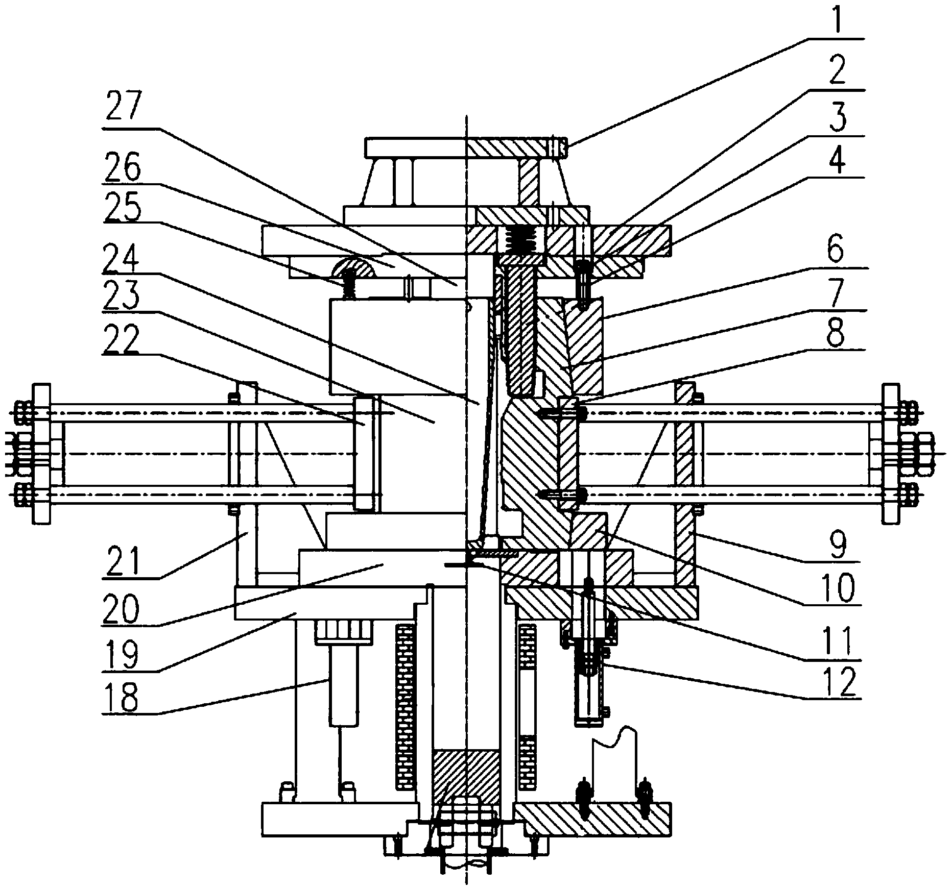
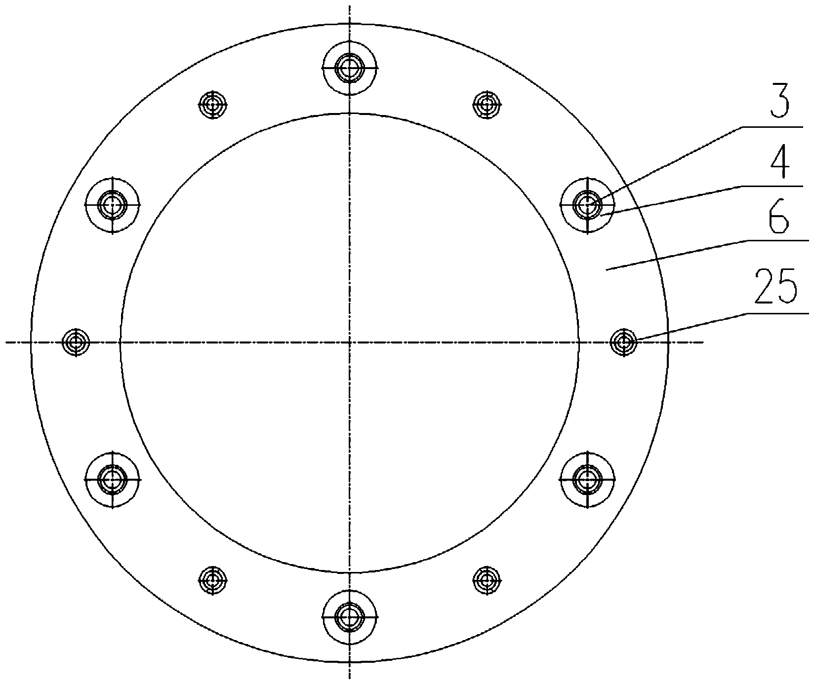
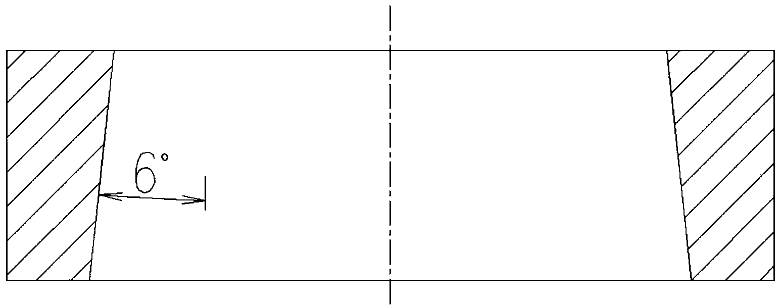
[0029] Such as figure 1 --3 shown. The clamping device of the direct squeeze casting mold of the present invention comprises a left side mold 23, a right side mold 7, a press worktable 19, and an upper mold plate 26; The upper mold clamping ring 6 and a lower mold clamping ring 10 sleeved on the outside of the right mold 7 and the left mold 23, the inner surface of the upper mold clamping ring 6 and the lower mold clamping ring 10 are in contact with the left mold 23 It is consistent with the angle of the tapered surface at the fitting position of the right mold 7, so that the molds can cooperate with each other when fitting to form a self-locking angle.

[0030] The clamping device also includes a right drive cylinder 12 and a left drive cylinder 18 for driving the lower clamping ring 10 to move;

[0031] The right drive cylinder 12 and the left drive cylinder 18 are symmetrically distributed and fixedly installed on the press worktable 19,

[0032] The lower clamping ring...


PUM


Abstract

The invention discloses a die locking device for directly extruding a casting die. The die locking device comprises an upper die locking ring and a lower die locking ring, wherein the upper die locking ring is arranged at the outer part of a right side die in a sleeving way, the lower die locking ring is arranged at the outer part of a left side die in the sleeving way, an annular inner surface of the upper die locking ring and the lower die locking ring is in a consistent angle with a conical surface of a mould assembling position of the left side die and the right side die, the left side die and the right side die can be mutually matched during mould assembling, and a self locking angle can be formed. When the left side die and the right side die are in the mould assembling in advance, the lower die locking ring moves to a side die lower mould assembling position under the driving of a lower die locking ring driving cylinder and is subjected to self locking, and the upper die locking ring moves to a side die upper mould assembling position under the driving of an upper die plate and is subjected to the self locking; a side die is locked after the upper die locking ring and the lower die locking ring reach the mould assembling position, a sealed cavity is formed by the upper die locking ring, the lower die locking ring, the side die, an upper die and a lower die together, and die assembling and mold filling are realized; after the mold filling, the upper die moves downwards for pressurizing, a connecting screw rod on the upper die locking ring returns to an upper die plate hole, movement separation of the upper die locking ring and the upper die is realized, and a die locking force during an extruding process is provided by the upper die locking ring and the lower die locking ring together.

Description

technical field [0001] The invention relates to the field of squeeze casting, in particular to a clamping device for a direct squeeze casting mold. Background technique [0002] Squeeze casting refers to forming and crystallizing and solidifying the liquid or semi-solid metal poured into the mold cavity under high mechanical pressure, so as to obtain high-quality parts with fine grains, dense internal structure and high surface finish. A forming method. At present, squeeze casting products both at home and abroad have a tendency to be large-scale, complex and lightweight. [0003] Due to the characteristics of large volume, complex shape structure, uneven wall thickness, and local forming difficulties, large and complex parts have the following characteristics and requirements when they are produced by direct extrusion casting forming process: [0004] (1) For the direct squeeze casting forming process of large and complex parts, in order to obtain a shaped casting with ex...

Claims


Application Information

Patent Timeline
IPC IPC(8): B22D18/02
Inventor 邵明张明伟张大童游东东
Owner SOUTH CHINA UNIV OF TECH
Why Eureka
Try Eureka