
Automatic overturning mechanism

An automatic turning and turning shaft technology, applied in vehicle maintenance, lifting vehicle accessories, transportation and packaging, etc., can solve the problems of increasing mechanism complexity and design difficulty, large installation space, etc., to achieve small installation space occupation and reliable operation , the effect of simple mechanism structure

Active Publication Date: 2014-11-12
GUIZHOU AEROSPACE TIANMA ELECTRICAL TECH
View PDF8 Cites 0 Cited by
  • Summary
  • Abstract
  • Description
  • Claims
  • Application Information

AI Technical Summary

Problems solved by technology

In order to drive the outriggers to turn over, these mechanisms also need to design auxiliary transmission chains, which increases the complexity and design difficulty of the mechanism, and requires a larger installation space. Generally, it is only used when the position of the outriggers seriously affects the departure angle and approach angle.

Method used


Image

  • Automatic overturning mechanism
  • Automatic overturning mechanism
  • Automatic overturning mechanism

Examples


Embodiment Construction

[0024] The technical solution of the present invention is further described below, but the scope of protection is not limited to the description.

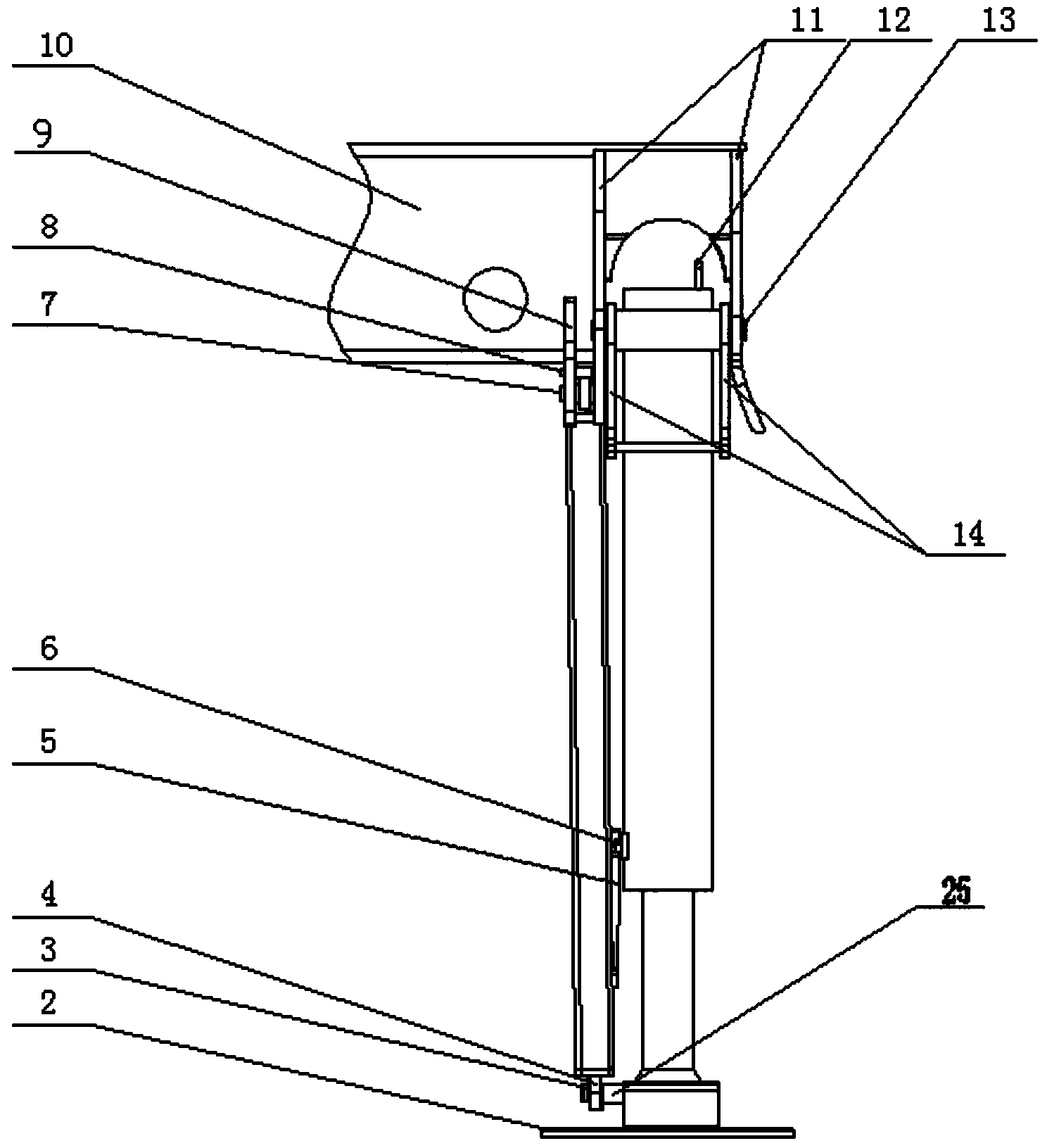
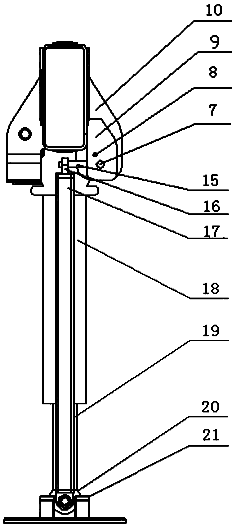
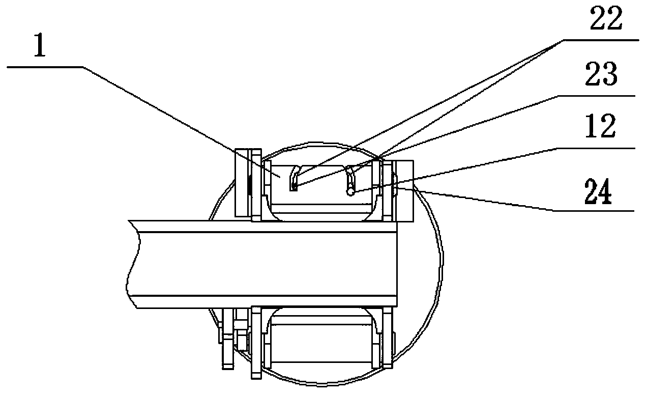
[0025] Such as Figure 1~3 The shown automatic turning mechanism includes: outrigger support plate 2, fixed lug 9, outrigger girder 10, left and right fixed support plates 11, outrigger turning shaft 13, telescopic tube 17, support plate ball hinge 20, ball Hinge retaining ring 21 and supporting legs; the upper end of the supporting legs is fixedly connected to the middle part of the supporting leg turning shaft 13, and the two ends of the supporting leg turning shaft 13 are inserted into the mounting holes of the left and right fixed support plates 11, and the left and right fixed support plates 11 and the supporting leg girder The ends of 10 are fixedly connected; the lower ends of the legs are fixedly connected with the support disk spherical hinge 20, and the support disk spherical hinge 20 is placed in the ball hinge stop ring...


PUM


Abstract

The invention provides an automatic overturning mechanism. The automatic overturning mechanism comprises a guiding sleeve, a supporting leg supporting disc, a fixed supporting lug, a supporting leg crossbeam, a left fixed supporting plate, a right fixed supporting plate, a supporting leg overturning shaft, a telescopic pipe, a supporting disc spherical hinge and a spherical hinge baffle ring, wherein the upper end of a supporting leg is fixedly connected to the middle part of the supporting leg overturning shaft; two ends of the supporting leg overturning shaft are inserted in installation holes in the left fixed supporting plate and the right fixed supporting plate, and the left fixed supporting plate and the right fixed supporting plate are fixedly connected with the end part of the supporting leg crossbeam; the lower end of the supporting leg is fixedly connected with the supporting disc spherical hinge, the supporting disc spherical hinge is arranged in the spherical hinge baffle ring, and the spherical hinge baffle ring is fixedly connected with the supporting leg supporting disc; the telescopic pipe is arranged at the left side of the supporting leg, an upper end supporting lug of the telescopic pipe is hinged to a telescopic pipe overturning short shaft through a telescopic pipe overturning arm, and a lower end supporting lug of the telescopic pipe is fixedly connected with the lower end of an inner pipe of the telescopic pipe. According to the hydraulic automatic overturning mechanism provided by the invention, the structure is simple, the working is reliable, the occupied installation space is small, and an additional driving force does not need to be provided.

Description

technical field [0001] The invention relates to an automatic turning mechanism. Background technique [0002] In order to avoid the influence of vehicle-mounted leveling outriggers on the departure angle and approach angle, the length and stroke of the oil cylinder are often designed to be large when designing the leveling outriggers, which seriously affects the installation space of the bodywork and increases the time for extending and withdrawing the legs. The design size of the oil tank of the hydraulic system has been increased. If the outrigger can be turned over to the top of the beam after the outrigger is withdrawn, it is not necessary to design the outrigger cylinder too long, and it will not affect the departure angle and approach angle. [0003] To realize the overturning of the outriggers, the rotary motion can be output through transmission forms such as gear transmission, chain transmission, and pulley mechanism. Among them, the gear transmission and chain tr...

Claims


Application Information

Patent Timeline
IPC IPC(8): B60S9/10
Inventor 向振文晏乾红樊战军吴地勇
Owner GUIZHOU AEROSPACE TIANMA ELECTRICAL TECH
Learn More