Catalytic cracking unit stripper

A technology of catalytic cracking unit and stripper, which is applied in catalytic cracking, cracking, petroleum industry, etc. It can solve the problems of difficult installation, overhaul and maintenance, prone to channeling of catalyst, and low utilization rate of effective space, etc. Fixed contact time, improved contact efficiency and mass transfer efficiency, and achieved full contact effect

Active Publication Date: 2014-11-12
LUOYANG PETROCHEMICAL ENG CORP SINOPEC +1
View PDF7 Cites 2 Cited by
  • Summary
  • Abstract
  • Description
  • Claims
  • Application Information

AI Technical Summary

Problems solved by technology

[0007] The purpose of the present invention is to provide a kind of stripper that is used for catalytic cracking unit, to solve the effective space utilization rate that the stripping equipment exists in the prior art is low, the catalyst is prone to channeling when flowing, complex structure, installation, Difficulty in overhaul and maintenance

Method used


Image

  • Catalytic cracking unit stripper
  • Catalytic cracking unit stripper
  • Catalytic cracking unit stripper

Examples


Embodiment

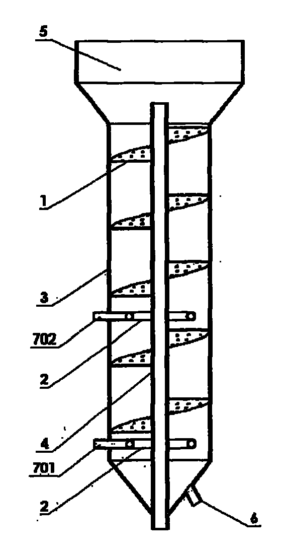
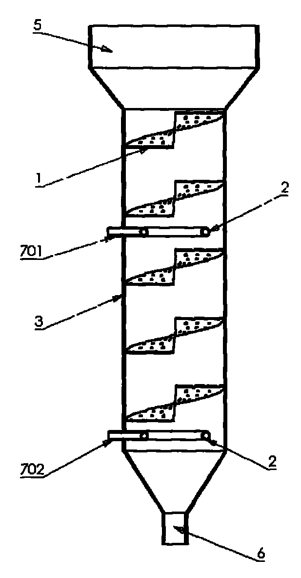
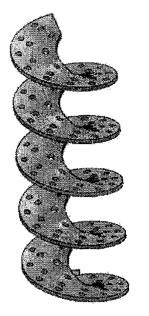
[0040] A 1 million ton / year FCC unit underwent renovation. Before the revamp, 6 sets of disc ring baffles and two-stage stripping steam distributor were used to strip the spent catalyst entrained with oil and gas from the settler. After the transformation, the spiral stripping baffles of the present invention were used to replace the 6-layer disk annular baffles before the transformation, and other structures (including two-stage stripping steam distributors) were not changed in any way. The spent catalyst from the settler entrains oil and gas into the top of the stripper. The spent catalyst first starts from the top of the equipment, flows downward through the spiral stripping baffle from top to bottom, and successively connects with the ascending first and second stages. The stripping steam is countercurrently contacted to replace the oil and gas entrained in the spent catalyst. The replaced oil gas and stripping steam flow upward into the settler, and then go to the fracti...


PUM

PropertyMeasurementUnit
diameteraaaaaaaaaa
heightaaaaaaaaaa
thicknessaaaaaaaaaa

Abstract

Belonging to the technological field of petroleum refining, the invention relates to a catalytic cracking unit stripper, which includes a stripper cylinder. Stripping baffles and stripping steam distributors are disposed in the stripper cylinder in the axial direction from top to bottom. The stripper is characterized in that: the stripping baffles are spiral stripping baffles and fixed on the inner wall of the stripper cylinder, and the spiral stripping baffles are provided with gas distribution holes. With the catalytic cracking unit stripper provided by the invention, a catalyst and stripping steam can be more uniformly distributed in the stripper, the gas-solid contact time is prolonged, the gas-solid countercurrent and cross flow contact can be increased, channeling in the catalyst in the stripper can be avoided, and the gas-solid backmixing degree in the stripper can be reduced, thereby realizing complete gas-solid contact and improving the contact efficiency and mass transfer efficiency of the catalyst and stripping steam.

Description

technical field [0001] The invention belongs to the technical field of petroleum refining, and in particular relates to a stripping equipment used in a petrochemical catalytic cracking and conversion device. Background technique [0002] In the fluidized catalytic cracking (FCC) settler, because the catalyst used is a porous substance, the catalyst particles and the micropores of the particles are filled with oil and gas, and this part of oil and gas accounts for about 2% to 4% of the total product. The coke equivalent to an increase of 2% to 4% is not removed, which reduces the yield of light oil; the research results show that if all the strippable oil and gas are stripped from the catalyst, the amount of coke will be reduced by 20 to 40%. Incompleteness increases the coke yield and increases the coking load of the regenerator, especially for heavy oil catalytic cracking. The coking capacity of the regenerator may become the controlling factor that limits the processing ca...

Claims


Application Information

Patent Timeline
Patent Type & Authority Applications(China)
IPC IPC(8): C10G11/16
Inventor 李国智马艳梅张振千王松江田耕
Owner LUOYANG PETROCHEMICAL ENG CORP SINOPEC
Why Eureka
Try Eureka