Supercharge Your Innovation With Domain-Expert AI Agents!

Machining stack structure and machining mode of light guide plates

A technology of stacking structure and light guide plate, which is applied in the direction of light guide, optics, optical components, etc., can solve the problems of waste of resources used in processing equipment, inability to guarantee work efficiency, etc., and achieve the effect of convenient operation, simple structure and wide application

Inactive Publication Date: 2014-11-12
SHENZHEN CHINA STAR OPTOELECTRONICS TECH CO LTD
View PDF10 Cites 0 Cited by
  • Summary
  • Abstract
  • Description
  • Claims
  • Application Information

AI Technical Summary

Problems solved by technology

However, only a single light guide plate is processed each time, which can neither guarantee work efficiency nor cause a great waste of resources used by processing equipment. It is necessary to consider a method to realize batch processing of light guide plates

Method used


Image

  • Machining stack structure and machining mode of light guide plates
  • Machining stack structure and machining mode of light guide plates
  • Machining stack structure and machining mode of light guide plates

Examples


Embodiment 1

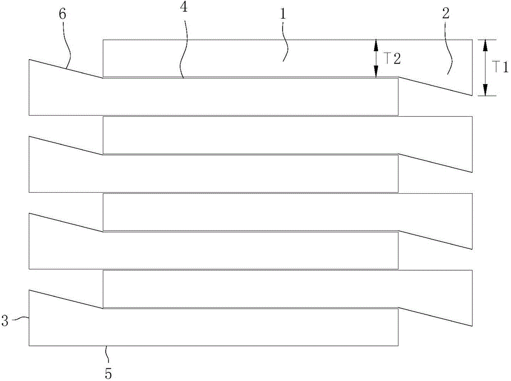
[0023] figure 1 The schematic diagram of the stacking state provided for this embodiment, the light guide plate is composed of the light guide plate main body 1 and the light incident side 2, wherein the thickness of the light guide plate main body 1 is uniform, and the integrally formed light incident side 2 is wedge-shaped, as shown in the figure, the following introduction Each side of the light guide plate mainly includes the light incident surface 3 and the inclined surface 6 of the light incident side 2 sequentially connected with the light incident surface 3, the light exit surface 4, the other side of the light incident surface is connected with the bottom surface 5, and the bottom surface 5 is connected with the light exit surface. Corresponding to surface 4, the thickness T1 of the light incident side 2 is less than twice the thickness T2 of the light guide plate main body 1, which is greater than the thickness T2 of the light guide plate main body 1. During processin...

Embodiment 2

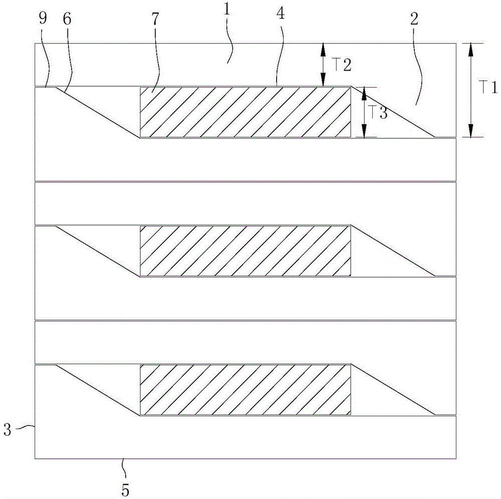
[0026] figure 2 A schematic diagram of the stacked state of another structural light guide plate provided for this embodiment. As shown in the figure, the thickness T1 of the light incident side 2 is greater than twice the thickness T2 of the light guide plate main body 1. If two When using light guide plates, the light incident side 2 of one of the light guide plates must be higher than the bottom surface 5 of the other light guide plate, which is not conducive to batch processing of the light guide plates. The structure of the light guide plate in this embodiment also includes the slope 6 of the light incident side 2 and The plane 9 between the light surfaces 3, the plane 9 is parallel to the bottom surface 5, and in this embodiment, when the light guide plates are stacked in pairs, the plane 9 on the light incident side 2 of one of the light guide plates is not the same as the light exit surface of the other light guide plate 4 are attached to each other, so that there mus...

Embodiment 3

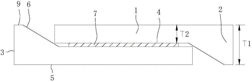
[0029] Such as image 3 As shown, the difference between this embodiment and embodiment 2 is that when two light guide plates are stacked, similar to embodiment 1, the light incident side 2 of one light guide plate is located on one side of the other light guide plate and its The top surface of the part higher than the light-emitting surface 4 of itself, that is, the plane 9, is equal to the bottom surface 5 of the other light guide plate, so that the distance between the light-emitting surfaces 4 of the two light guide plates can be reduced, and the volume of the backing plate 7 in the middle can be made Even smaller, when multiple such light guide plates are stacked, the volume will be effectively reduced. In this embodiment, the thickness T3 of the backing plate is greater than the sum of the thickness T1 of the light-incident side and the thickness T2 of the main body of the light guide plate. Friction between light plates.


PUM


Abstract

The invention discloses a machining stack structure of light guide plates. Each light guide plate comprises a light guide plate body and a light entering side, wherein the thickness T1 of the light entering side is larger than the thickness T2 of the light guide plate body. The machining stack structure is characterized in that when the light guide plates are machined, two light guide plates are exchanged in position and stacked and then more light guide plates which are stacked in pairs are stacked. The machining stack structure of the light guide plates can adapt to change in thickness of the light entering side and change in a wedge shape, it is guaranteed that the stacked light guide plates are orderly and leveled, the light guide plates can be cut and polished in batches, and the machining stack structure is simple in structure, convenient to operate, and wide in application.

Description

technical field [0001] The invention relates to the processing field of light guide plates, in particular to batch cutting and polishing of light guide plates. Background technique [0002] The light guide plate is a high-tech plate with extremely high reflectivity and no light absorption. According to the shape of the light guide plate, it can be divided into: flat light guide plate and light guide plate. The thickness of the light incident side of the light guide plate is greater than that of the main body of the light guide plate. In the manufacturing process, the finished product is completed by cutting and polishing process, which has the characteristics of simple process and convenient manufacture. However, only a single light guide plate is processed each time, which can neither guarantee work efficiency nor cause a great waste of resources used by processing equipment. It is necessary to consider a method to realize batch processing of light guide plates. Contents...

Claims


Application Information

Patent Timeline
IPC IPC(8): G02B6/00
CPCG02B6/00
Inventor 贺虎
Owner SHENZHEN CHINA STAR OPTOELECTRONICS TECH CO LTD
Features
  • R&D
  • Intellectual Property
  • Life Sciences
  • Materials
  • Tech Scout
  • Unparalleled Data Quality
  • Higher Quality Content
  • 60% Fewer Hallucinations
Learn More