Supercharge Your Innovation With Domain-Expert AI Agents!

Control method for fast cutting of spraying rail

A control method and rapid cutting technology, applied in the field of mechanical processing, can solve the problems of time-consuming cutting, low safety and reliability, etc., and achieve the effects of protecting the saw blade, reducing energy consumption, and preventing safety accidents

Inactive Publication Date: 2017-03-29
陈蕾
View PDF0 Cites 0 Cited by
  • Summary
  • Abstract
  • Description
  • Claims
  • Application Information

AI Technical Summary

Problems solved by technology

[0004] The invention provides a control method for rapid cutting of spray rails to solve the problems of time-consuming, energy consumption and low safety and reliability of single-piece cutting of spray rail cutting machines, and achieve the purpose of safe and efficient batch cutting

Method used


Image

  • Control method for fast cutting of spraying rail

Examples


Embodiment 1

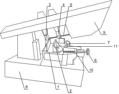
[0020] Such as figure 1 As shown, the present invention first places the spray rail on the cutting machine, and then adjusts the spray rail clamping mechanism to move close to or away from the position in the direction of the saw blade through the adjustment mechanism. Move to meet the needs of cutting the spray rail, the spray rail clamping mechanism can hold one or more than one spray rail main material, turn the second hand wheel to make the spray rail main material move to the direction of the saw blade, start the band saw machine, Complete the cutting of the spray rail; the band saw machine is set on the mechanical arm 9, and the mechanical arm 9 is connected to the machine tool 8, including the spray rail clamping mechanism 1 and the adjustment mechanism, and the spray rail clamping mechanism 1 is slidably set on the machine tool 8 for operation On the stage, the spray rail clamping mechanism 1 is connected with the adjusting mechanism provided on the machine tool 8 . T...

Embodiment 2

[0022] Such as figure 1 As shown, in this embodiment, on the basis of Embodiment 1, the first hand wheel 6 is rotated, so that the movable baffle 2 moves to the right, and the distance between the fixed baffle 3 is increased to place more cutting main materials, After the spray rail main material is placed on the spray rail clamping mechanism 1 in batches, the first hand wheel 6 is rotated to make the spray rail clamping mechanism 1 clamp the main material.

Embodiment 3

[0024] Such as figure 1 As shown, the present embodiment is on the basis of Embodiment 1, and the adjustment mechanism includes a second hand wheel 7 and a second screw 10, the second screw 10 is arranged on the operating table of the machine tool, and the second screw 10 and the operating table of the machine tool are threaded, one end of the second screw rod 10 is connected with the second handwheel 7, the other end of the second screw rod 10 is in contact with the connecting plate, and the second handwheel 7 passes through the second screw rod 10 links to each other with spray rail clamping mechanism 1. Through the connecting plate, the second screw rod 10 connects the spray rail clamping mechanism 1 with the second hand wheel 7, and rotating the second hand wheel 7 can make the spray rail clamping mechanism 1 move freely in the direction close to or away from the saw blade 5, To facilitate saw blade 5 cutting.


PUM


Abstract

The invention discloses a control method for fast cutting of a spraying rail. The control method comprises the steps that first, the spraying rail is placed on a cutting machine; a spraying rail clamping mechanism is adjusted through an adjustment mechanism to move in the direction close to or away from a saw blade; a mechanical arm is installed on a machine tool and can move up and down by means of a supporting point so as to meet requirement for cutting of the spraying rail; the spraying rail clamping mechanism can clamp one or more spraying rail main materials, and a second hand wheel is rotated to enable the spraying rail main materials to move towards the saw blade; and a band-sawing machine is started, and cutting of the spraying rail is completed.

Description

technical field [0001] The invention relates to the field of mechanical processing, in particular to a control method for rapid cutting spray rails. Background technique [0002] At present, the commonly used gas control system is the multi-point sequential injection gas supply system. The working principle of the CNG multi-point sequential injection system: when the system is working, the gas computer inputs the signal based on the fuel injection signal of the original vehicle (gasoline control system), and at the same time obtains the engine water temperature, gas temperature and gas pressure and other parameters after correction, and determines the timely injection The gas injection pulse width is supplied by the gas injection rail to the corresponding engine cylinder. Generally, the engine is started with gasoline. When the engine is running and the transfer switch is set to gas mode, the gas computer will automatically detect the conversion conditions stored in the com...

Claims


Application Information

Patent Timeline
Patent Type & Authority Applications(China)
IPC IPC(8): B23D55/04B23D55/00
Inventor 陈蕾
Owner 陈蕾
Features
  • R&D
  • Intellectual Property
  • Life Sciences
  • Materials
  • Tech Scout
  • Unparalleled Data Quality
  • Higher Quality Content
  • 60% Fewer Hallucinations
Learn More