
A dual-band optical system imaging device

An optical system and imaging device technology, applied in optics, optical components, instruments, etc., can solve the problems of loss of detector capability and decrease of system sensitivity, and achieve the effect of reducing the influence of central occlusion, compact structure, and ensuring sensitivity

Active Publication Date: 2017-09-22
BEIJING RES INST OF SPATIAL MECHANICAL & ELECTRICAL TECH
View PDF5 Cites 0 Cited by
  • Summary
  • Abstract
  • Description
  • Claims
  • Application Information

AI Technical Summary

Problems solved by technology

The dual-band optical systems reported above all use a spectroscope in the back optical path of the main reflector to split the light, thus forming a dual channel, so that the ability to reach each detector is seriously lost, resulting in a decrease in the sensitivity of the system, and the influence of central occlusion

Method used


Image

  • A dual-band optical system imaging device

Examples


Embodiment Construction

[0013] The present invention will be described in further detail below in conjunction with the accompanying drawings.

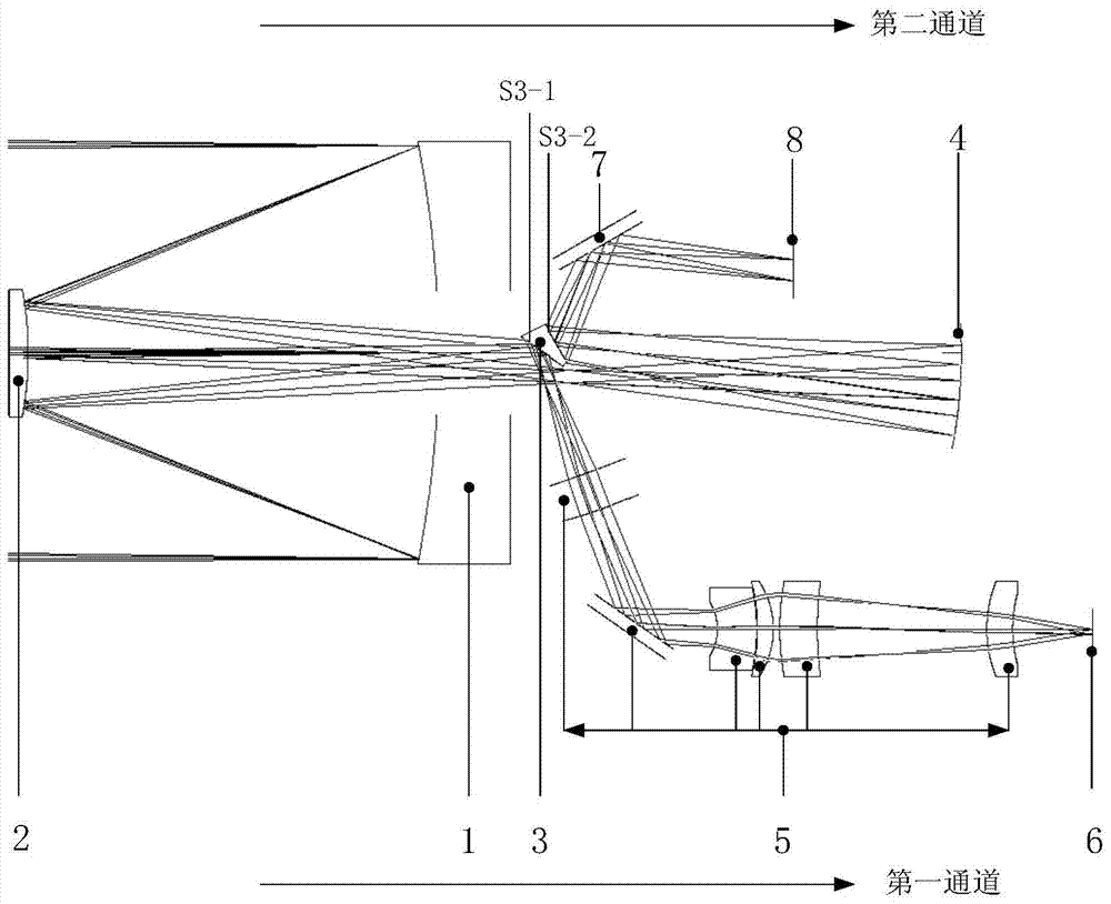
[0014] Such as figure 1 As shown, a dual-band optical system imaging device of the present invention includes a first channel and a second channel, wherein a channel and the second channel share a primary mirror 1 and a secondary mirror 2, and the primary mirror 1 and the secondary mirror 2 are all Designed as hyperboloids to form the classic Cassegrain system. The wedge mirror 3 is placed at the position of the primary image emitted from the secondary mirror 2 .

[0015] The optical system of the first channel includes a primary mirror 1, a secondary mirror 2, a wedge mirror 3, a lens group 5 and a first focal plane 6 in order from the object side to the image side; the light of the channel 1 passes through the primary mirror 1, the secondary The mirror 2 is reflected by the lower side S3-1 of the wedge mirror 3, and is focused and imaged on the first foca...


PUM


Abstract

The invention discloses a double-waveband optical system imaging device which comprises a first channel and a second channel. A main mirror (1) and a secondary mirror (2) which are shared by the two channels form a classic Cassegrain system. A wedge-shaped mirror (3) is placed at the position of a primary image emitted by the secondary mirror (2). Light rays of the first channel sequentially pass through the main mirror (1) and the secondary mirror (2), are reflected by a lower side face S3-1 of the wedge-shaped mirror (3) and are then focused and imaged on a first focal plane (6) through a lens assembly (5). Light rays of the second channel sequentially pass through the main mirror (1), the secondary mirror (2) and a reflector (4), are reflected by an upper side face S3-2 of the wedge-shaped mirror (3) and are then turned and imaged on a second focal plane (8) through a plane mirror (7). According to the double-waveband optical system imaging device, the wedge-shaped mirror is added to be back of the main mirror, light rays are reflected and divided by the two faces of the wedge-shaped mirror to form two paths, and double-waveband work is achieved; meanwhile, by means of a bias view field optical system, energy arriving at a detector is not lost, and sensitivity of the system is ensured.

Description

technical field [0001] This patent belongs to an optical imaging system, in particular to an imaging device of an off-field optical system that uses reflection on both sides of a wedge mirror to form a dual channel. Background technique [0002] With the development of camouflage technology, reconnaissance and identification of targets are becoming more and more difficult, and single-band reconnaissance can no longer meet the needs of development. Due to the large difference in the optical characteristics of targets in different spectral bands, dual bands can be used to achieve all-weather, high-resolution target reconnaissance. [0003] In the previously reported dual-band optical system, a beam splitter is usually added to the optical path behind the main reflector to split the light to form a dual channel. For example, in the design of infrared dual-band Cassegrain optical system, Fan Xuewu, Ma Zhen, et al. reported in (Acta Photonica Sinica) (Acta Photonica Sinica) (200...

Claims


Application Information

Patent Timeline
Patent Type & Authority Patents(China)
IPC IPC(8): G02B17/02
Inventor 李福东曹桂丽林招荣葛婧菁朱大凯
Owner BEIJING RES INST OF SPATIAL MECHANICAL & ELECTRICAL TECH
Learn More