Air compression type arc extinction device and high-voltage circuit breaker with arc extinction device

An arc extinguishing device and cylinder pressure technology are applied in the fields of high-voltage circuit breakers and compressed air arc extinguishing devices, which can solve the problems of high structural performance and operating device requirements of arc extinguishing devices, large operating power, etc., so as to prolong the service life and facilitate the Effects of Manufacturing and Assembly

Active Publication Date: 2014-11-12
STATE GRID CORP OF CHINA +2
View PDF8 Cites 7 Cited by
  • Summary
  • Abstract
  • Description
  • Claims
  • Application Information

AI Technical Summary

Problems solved by technology

However, when the switch is closed, the moving arc contact moves toward the static arc contact and is sleeved on the static arc contact. At the same time, the nozzle is also sleeved on the static arc contact. The air flow channel formed by the opening at the front end of the head is blocked by the static arc contact. When opening, the air flow channel at the moving arc contact is officially opened only when the static arc contact leaves the moving arc contact and starts to pull the arc. Then The airflow channel of the nozzle is opened. Since the two airflow channels are blocked in the initial stage of opening, the reverse force of gas compression and the force of the arc will be concentrated together, resulting in a large amount of operating work required in the initial stage of opening. The structural performance and operating device of the arc extinguishing device have high requirements

Method used


Image

  • Air compression type arc extinction device and high-voltage circuit breaker with arc extinction device
  • Air compression type arc extinction device and high-voltage circuit breaker with arc extinction device
  • Air compression type arc extinction device and high-voltage circuit breaker with arc extinction device

Examples


Embodiment Construction

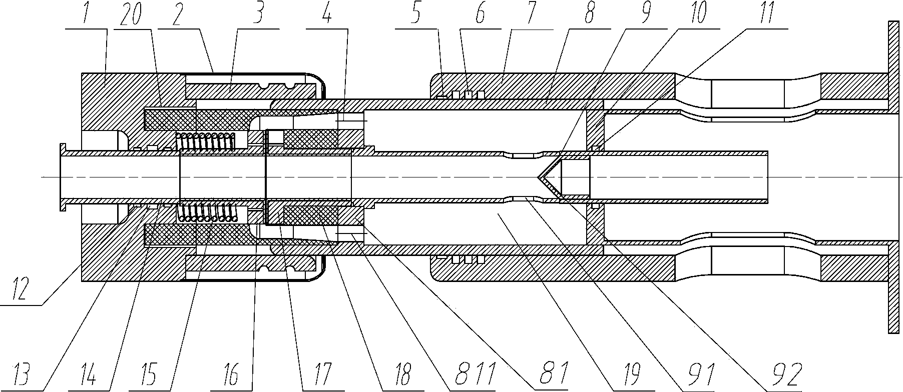
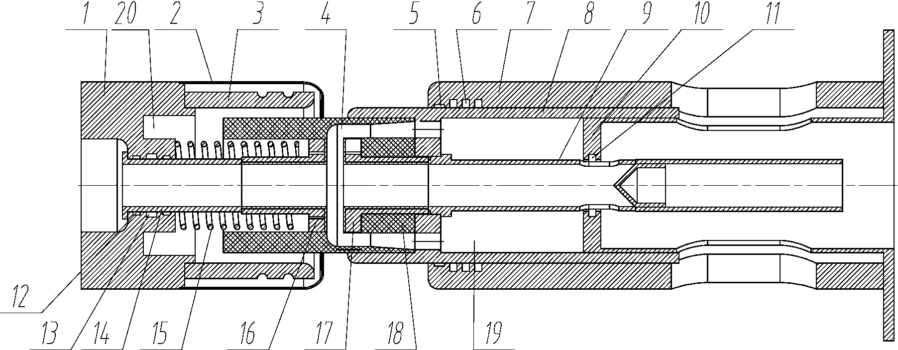
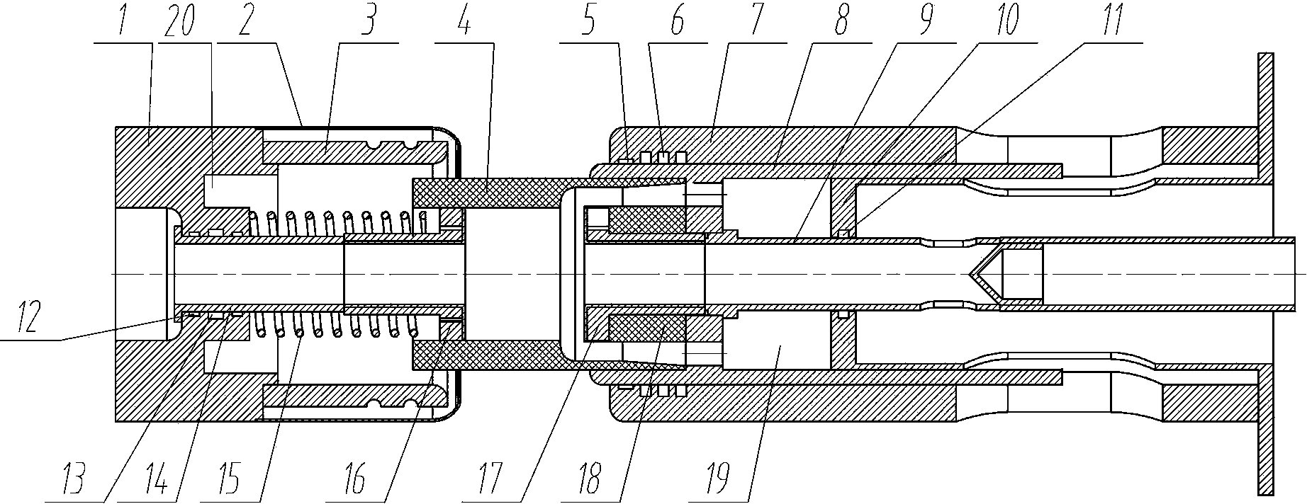
[0024] An embodiment of the medium pressure gas arc extinguishing device of the present invention is Figure 1~Figure 6 shown, is a SF 6 The arc extinguishing chamber includes a static end assembly and a moving end assembly, wherein the static end assembly includes a static contact seat 1, a static end shield 2, a static main contact 3 and a static arc contact 16, and the moving end assembly includes a moving end conductor 7, The support base 10 and the pressure cylinder 8, nozzle 4, moving arc contact 17 and pull rod 9 fixedly assembled together, the end of the pressure cylinder 8 close to the static end assembly constitutes the moving main contact for conducting with the static main contact 3 head.

[0025]The assembling method of the static contact seat 1 , the static end shield 2 and the static main contact 3 is the prior art, and will not be described in detail here. The static arc contact 16 includes a contact cylinder 21 with an axial through hole, and a flange extend...


PUM


Abstract

The invention relates to an air compression type arc extinction device and a high-voltage circuit breaker with the arc extinction device. The air compression type arc extinction device comprises a movable arc contact, a static arc contact, a nozzle, an air cylinder and a static contact base. The arc ends of the movable arc contact and the static arc contact are both provided with butt joint conductive end faces which face each other and are in opposite press fit in a switch-on state. The static arc contact is assembled on the static contact base in a guided and movable mode through a conductive rod in the switch-off and switch-on directions and is conductively connected with the static contact base. An over-travel spring is arranged between the static arc contact and the static contact base. The conductive rod is provided with a static arc contact anti-disengaging structure. At least one of the two arc contacts is provided with an axial through hole. The end, opposite to the corresponding butt joint conductive end face, of the axial through hole is communicated with an air chamber outside the air cylinder through a communication channel. The nozzle is provided with a clearance fit section which is in clearance fit with the corresponding outer circumferential face of the static arc contact in the switch-off and switch-on travels. According to the air compression type arc extinction device, the movable arc contact and the static arc contact can be prevented from being abraded in the switch-off and switch-on processes and the requirement for coaxiality can be lowered when the movable arc contact and the static arc contact are assembled.

Description

technical field [0001] The invention relates to a compressed gas arc extinguishing device and a high-voltage circuit breaker using the arc extinguishing device. Background technique [0002] Common non-vacuum high-voltage circuit breakers are generally compressed air arc extinguishing devices, which adopt the blowing arc extinguishing method, relying on the relative movement of the compressed air cylinder and the piston to make high-pressure gas eject from the nozzle to blow off the arc. For example, a Chinese patent with application number 201020609730.9 and authorized announcement date of 2011.06.08 discloses an outdoor high-voltage AC porcelain column SF 6 A circuit breaker includes a housing, a static end assembly and a moving end assembly. The static end assembly includes a static contact seat, a static main contact and a static arc contact installed on the static contact seat. The moving end assembly includes a fixed and The pressure cylinder, the moving contact seat,...

Claims


Application Information

Patent Timeline
Patent Type & Authority Applications(China)
IPC IPC(8): H01H33/91
Inventor 林麟程铁汉张博李丽娜金光耀李艳郭煜敬张友鹏王振李良权
Owner STATE GRID CORP OF CHINA
Why Eureka
Try Eureka