High-resolution camera different-field-of-view integral time determination method

A technology of integrating time and determining the method, which is applied in the field of optical remote sensing, and can solve the problems of not considering the influence of camera installation angle and satellite attitude angular velocity, mismatching of actual time, and not considering pole shift, etc.

Active Publication Date: 2014-11-12
AEROSPACE DONGFANGHONG SATELLITE
View PDF4 Cites 12 Cited by
  • Summary
  • Abstract
  • Description
  • Claims
  • Application Information

AI Technical Summary

Problems solved by technology

[0015] (1) The integration time calculation model does not consider the situation that the camera boresight is inconsistent with the optical axis. However, the widely used high-resolution camera boresight and optical axis are inconsistent, and there is an off-field angle, which will lead to the calculated integral The time does not match the actual time the image on the camera's focal plane moves one line
[0016] (2) The calculation model of integration time cannot be directly used to calculate the integration time of different fields of view of the camera, and the current high-resolution satellites have an urgent demand for the calculation of the integration time of different fields of view of the camera
[0017] (3) The calculation of the speed-to-height ratio of the photographing point in the integral time calculation model is generally calculated by a simplified formula for the side swing state, and does not consider the influence of the camera installation angle and the satellite attitude angular velocity, but the high-resolution image with agile characteristics The satellite has both roll and pitch imaging states and attitude maneuvers, which require rigorous calculation models
[0018] (4) During the implementation of the integration time calculation, whether it is the STK-based simulation calculation in the laboratory or the satellite in-orbit calculation, the pole shift, time system difference, precession and nutation model error, and low-resolution digital elevation model (DEM) are not considered. Even without DEM and other earth characteristic factors, the accuracy of the calculated integration time is low

Method used


Image

  • High-resolution camera different-field-of-view integral time determination method
  • High-resolution camera different-field-of-view integral time determination method
  • High-resolution camera different-field-of-view integral time determination method

Examples


Embodiment Construction

[0087] The present invention will be further described below in conjunction with the accompanying drawings.

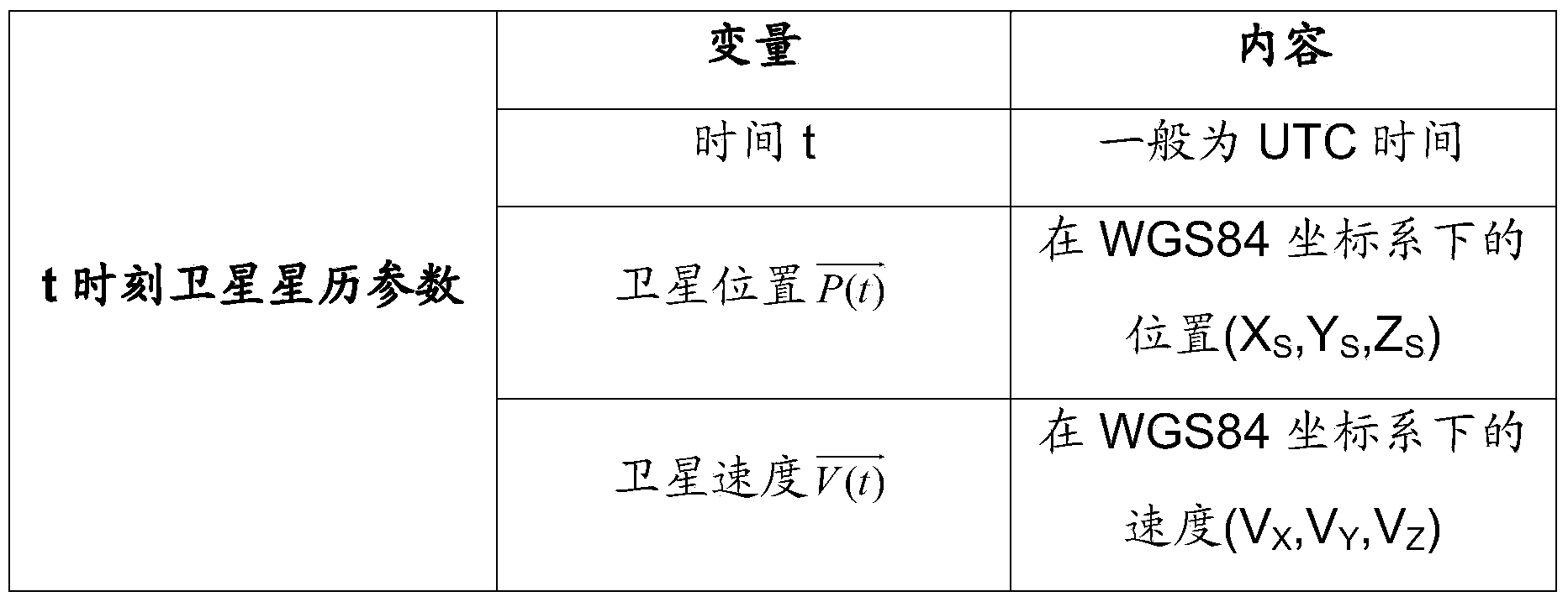
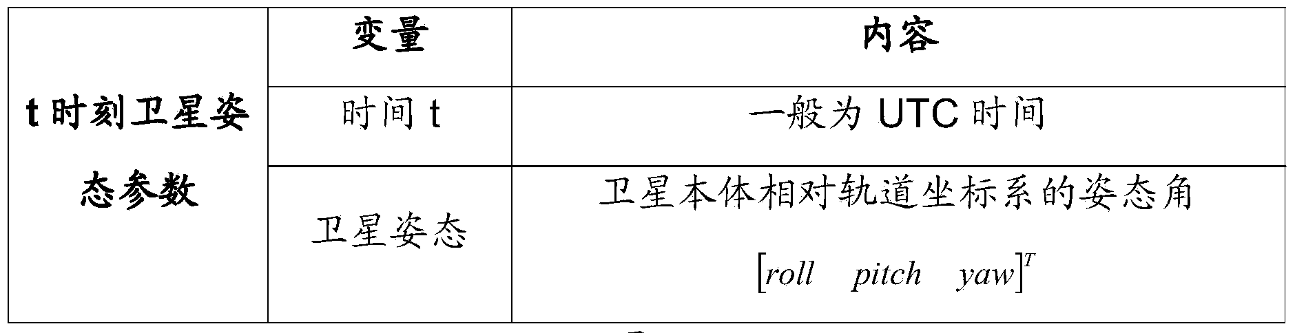
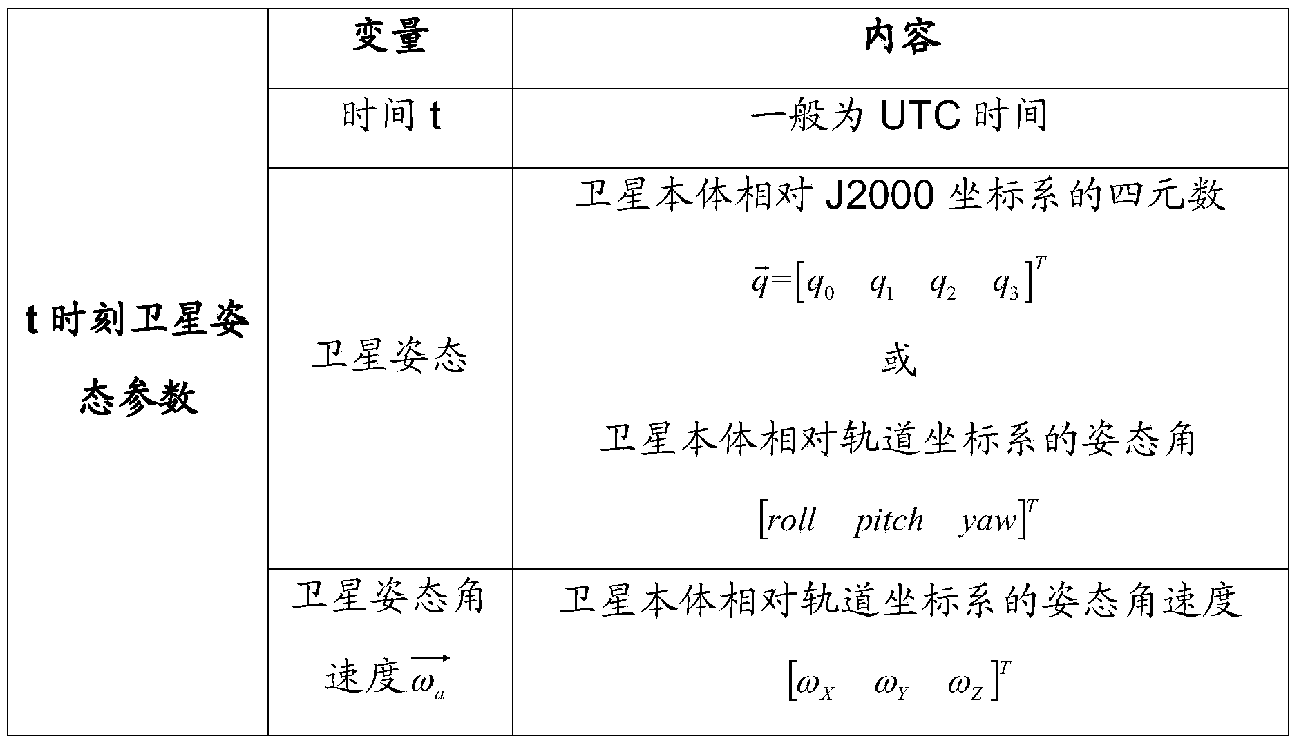
[0088] First determine the relevant parameters of the camera needed to accurately calculate the integration time, and press Figure 4 Determine the Ф and θ angles corresponding to the θ field of view of the camera, press figure 1 with image 3 Prepare satellite ephemeris parameters and satellite attitude parameters respectively; then follow Figure 5 Realize the conversion of camera θ field of view to WGS84 coordinate system, according to Image 6 with Figure 7 The camera θ field of view corresponding to the line of sight is intersected with the earth ellipsoid in the WGS84 coordinate system to determine the geographic coordinates of the photography point, and the slant distance of the photography point can be obtained according to the geographic coordinates of the photography point and the satellite position. In addition, according to Figure 8 Calculate the mov...


PUM


Abstract

The invention provides a high-resolution camera different-field-of-view integral time determination method. Firstly, the related parameters of a camera required for accurately calculating integral time are determined, the phi angle and theta angle corresponding to a camera theta field of view are determined, and satellite ephemeris parameters and satellite attitude parameters are prepared respectively; conversion from the camera theta field-of-view visual direction into the WGS84 coordinate system is achieved, the visual direction corresponding to the camera theta field of view is intersected with the earth ellipsoid under the WGS84 coordinate system to determine the geographical coordinates of a photography point, and the photography point slope distance can be obtained according to the photography point geographical coordinates and the satellite position. Furthermore, the motion speed of the corresponding photography point of the camera theta field of view under the J2000 coordinate system is calculated, and the conversion relation from the camera to the WGS84 coordinate system is combined, and the photography point image motion can be determined. Finally, according to the worked out photography point slope distance and the photography point image motion, the integral time of the corresponding photography point of the camera theta field of view can be obtained according to an integral time calculation model in the method.

Description

technical field [0001] The invention belongs to the field of optical remote sensing and relates to a method for determining the integration time of different fields of view of a high-resolution camera. Background technique [0002] At present, high-resolution cameras generally adopt TDI push-broom imaging technology, so that the camera can not only obtain excellent image quality, but also realize the light and small design of the camera. [0003] For a camera with push-broom imaging, the time required for the image formed by the ground object on the focal plane to move one line is the line cycle of the camera, and the time for the charge packet generated by the CCD to transfer once is the camera integration time. Usually, the maximum value of the camera integration time is is the line period of the camera. In order to ensure that the camera system has a high signal-to-noise ratio, the camera integration time is generally designed to be equal to the line period, that is, the...

Claims


Application Information

Patent Timeline
Patent Type & Authority Applications(China)
IPC IPC(8): H04N5/353
Inventor 赵鸿志王付刚孙峻曹启鹏朱军于生全
Owner AEROSPACE DONGFANGHONG SATELLITE
Why Eureka
Try Eureka