
Combined multifunctional filtering device

A filtering device and multi-functional technology, which is applied in the field of composite multi-functional filtering devices, can solve the problems of increasing the head loss of the filtering system, increasing the power of the first matching water pump, and reducing the use efficiency of equipment, so as to achieve uniform fertilization, aeration and backwashing, The effect of reducing auxiliary equipment and high degree of automation

Active Publication Date: 2014-11-19
江苏迪迈机械有限公司
View PDF5 Cites 13 Cited by
  • Summary
  • Abstract
  • Description
  • Claims
  • Application Information

AI Technical Summary

Problems solved by technology

A single filter can only achieve a single filtering function, and the actual filtering needs can only be met after combined application
However, there are many disadvantages in the filter group used in combination. The increase in the number of filter stages will inevitably increase the difficulty of pipeline connection, and the variety of pipe fittings will increase the system cost and increase the space occupied by the equipment.
The increase of pipe fittings, the growth of pipelines, and the bending of water flow channels increase the head loss of the filtration system, which increases the power of the first matching water pump.
At the same time, after a period of time, the multi-stage filter needs to be rinsed. The more stages there are, the more water will be consumed for separate flushing, which increases the frequency of flushing and also causes a lot of waste of water resources, which reduces the efficiency of equipment.
At the same time, the existing fertilization method is mainly to inject fertilizer in the pipeline. In many cases, the fertilizer cannot be fully mixed with water after injection, resulting in some plots with more fertilizer and some plots with less fertilizer, resulting in uneven fertilizer injection. question

Method used


Image

  • Combined multifunctional filtering device
  • Combined multifunctional filtering device
  • Combined multifunctional filtering device

Examples


Embodiment Construction

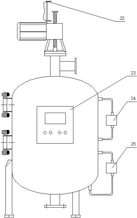
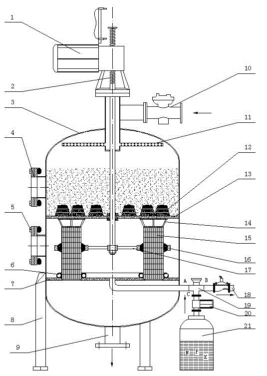
[0008] Embodiments are described in detail with reference to the accompanying drawings. A composite multifunctional filtering device, the inside of the tank body 3 is divided into upper, middle and lower layers from top to bottom, the upper layer is a sand medium filter chamber, the middle is a wedge-shaped mesh filter chamber, and the lower part is a clear water collection chamber.

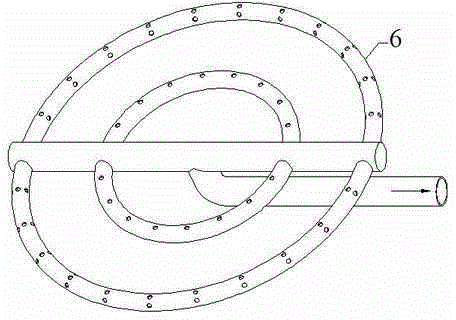
[0009] The sand medium filter cavity is set in the upper space of the upper partition 13, and the water distributor 11 is installed at the upper water inlet of the tank body 3 to disperse the incoming water as evenly as possible, so that the water containing impurities can evenly fall on the sand. The surface of the stone medium filter layer avoids stirring of the filter layer due to the concentrated impact of the water flow on the sand medium filter layer, which affects the filtering effect. The side wall of the tank body 3 is provided with a sand hole 4 . A layer of filter cap 12 is arranged at...


PUM


Abstract

The invention discloses a combined multifunctional filtering device, belonging to the technical field of filtration. The key points of the technical scheme are as follows: a tank body of the combined multifunctional filtering device is internally separated into a sand stone medium filtering cavity, a wedge-shaped net-type filtering cavity and a clean water collecting cavity by an upper baffle and a lower baffle sequentially from top to bottom; the outer side of the tank body is provided with an upper pressure-difference switch, a lower pressure-difference switch and a control cabinet respectively; the bottom of the tank body is provided with a tank body support frame. The combined multifunctional filtering device is compact in structure, and meanwhile has advantages of the sand stone medium filter and a brush-type cleaning filter, the occupied area is small, the water flow is smooth, the head loss is low, and the automation degree is high, meanwhile, uniform fertilize uniformity and air entrapping backflushing can be realized, the device utilization ratio is increased, the number of auxiliary equipped devices is reduced, and the cost is saved.

Description

technical field [0001] The invention belongs to the technical field of filtration, and in particular relates to a composite multifunctional filtration device. Background technique [0002] At present, the filters used in the field of agricultural irrigation mainly include laminated filters, sand media filters, centrifugal filters and mesh filters. Sheet filter, centrifugal filter with laminated filter, sand filter with mesh filter, etc. A single filter can only achieve a single filtering function, and the actual filtering needs can only be met after combined application. However, there are many disadvantages in the filter group used in combination. The increase in the number of filter stages will inevitably increase the difficulty of pipeline connection, and the variety of pipe fittings will increase the cost of the system and increase the space occupied by the equipment. The increase of pipe fittings, the increase of pipes, and the bending of the water flow path increase ...

Claims


Application Information

Patent Timeline
IPC IPC(8): B01D36/02
Inventor 翟国亮蔡九茂李莉宗洁张文正李景海邓忠李迎任方
Owner 江苏迪迈机械有限公司
Learn More