Automatic adjustment structure for flanging sub mold or extending sub mold

An automatic adjustment and edge sub-mold technology, applied in metal processing equipment, forming tools, manufacturing tools, etc., can solve the problems of affecting debugging efficiency, time-consuming and laborious, and achieve the effects of convenient use, automatic adjustment, and simple structure.

Active Publication Date: 2014-11-19
WUXI MICRO RES
View PDF5 Cites 1 Cited by
  • Summary
  • Abstract
  • Description
  • Claims
  • Application Information

AI Technical Summary

Problems solved by technology

This kind of frequent adjustment of the height of the flanging punch 105 during the mold trial is time-consuming and laborious, which greatly affects the debugging efficiency

Method used


Image

  • Automatic adjustment structure for flanging sub mold or extending sub mold
  • Automatic adjustment structure for flanging sub mold or extending sub mold
  • Automatic adjustment structure for flanging sub mold or extending sub mold

Examples


Embodiment Construction

[0023] The specific implementation manner of the present invention will be described below in conjunction with the accompanying drawings.

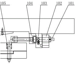
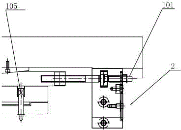
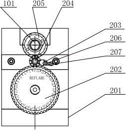
[0024] A self-adjusting structure for flanging sub-moulds or extension sub-moulds, such as Figure 3 to Figure 7 As shown, the automatic adjustment mechanism 2 includes a housing 201, the screw rod 101 runs through the housing 201, and a first oil cylinder cavity 208 and a second oil cylinder cavity 209 are respectively arranged in the housing 201, and are installed in the first oil cylinder cavity 208. The first piston 212, the end of the first piston 212 is hinged to the first top block 211, and the first top block 211 abuts against the first ratchet 210; The end of the second top block 214 is hinged, and the second top block 214 and the second ratchet 213 abut against each other; the first ratchet 210 and the second ratchet 213 are both socketed with the screw 101, and the first moment is also connected to the screw 101. The dial 205 ;...


PUM


Abstract

The invention relates to an automatic adjustment structure for a flanging sub mold or an extending sub mold. The automatic adjustment structure comprises a shell, wherein a screw rod penetrates through the shell, and a first oil cylinder cavity and a second oil cylinder cavity are arranged in the shell respectively. A first piston is arranged in the first oil cylinder cavity, a first ejector block is connected with the end of the first piston, and the first ejector block is connected with a first ratchet wheel in an abutting mode. The automatic adjustment structure is simple in structure and convenient to use, two oil cylinders in the shell are used for driving two ratchet wheels to rotate in different directions to achieve moving of the screw rod, finally vertical moving of the flanging convex mold is achieved, and automatically adjustment of the flanging height is achieved, so that the laminated heights of the whole fins of a heat exchanger are uniform. Meanwhile, in the moving process of the screw rod, by means of the transmission mode of gear meshing, a dial records the flanging height, a rotation stopping block is arranged to prevent the revolution number of a gear from being too large, and the phenomenon that the dial can not accurately record subsequently is avoided.

Description

technical field [0001] The invention relates to processing equipment for air-conditioning fins, in particular to an automatic adjustment structure for flanging sub-moulds or extension sub-moulds. Background technique [0002] The air conditioner condenser is used in refrigeration and air conditioning systems. The refrigerant liquid in the tube directly exchanges heat with the air outside the tube to achieve the effect of cooling the air. At present, the overall height of the existing air-conditioning condenser and the tightness of the fins are determined by the flanging height of the fins. Therefore, the flanging height of the fins directly affects the quality of use of the heat exchanger. Such as figure 1 Shown is the structure of the existing adjustment mechanism: the rotating screw rod 101 is screwed in the first screw rod fixing block 103, the second screw rod fixing block 104, and the counter 102, and the front and rear displacement is controlled by rotating the screw ...

Claims


Application Information

Patent Timeline
Patent Type & Authority Applications(China)
IPC IPC(8): B21D37/10B21D19/00
Inventor 王静娴
Owner WUXI MICRO RES
Why Eureka
Try Eureka