
Automatic component overturning demolding machine

The technology of a demoulding machine and a demoulding mechanism, which is applied in the field of demoulding machines, can solve the problems of time-consuming and laborious, reduced production efficiency, and low production efficiency, and achieve the effects of avoiding manual operation, concise mechanical actions, and reducing labor intensity

Active Publication Date: 2014-11-19
JINAN DONGYUAN CEMENT PROD CO LTD
View PDF7 Cites 9 Cited by
  • Summary
  • Abstract
  • Description
  • Claims
  • Application Information

AI Technical Summary

Problems solved by technology

[0002] Small plastic concrete components are still produced by manual pouring, which has low production efficiency and cannot meet the short-term and large-scale procurement needs
In the manual pouring production process, when the components need to be demoulded, the mold with the components is usually lifted manually, then the mold is manually turned over, and then manually touched to the ground to knock out the components in the mold, which is not only time-consuming and labor-intensive, but also increases Reduce the labor intensity of workers and reduce production efficiency
[0003] Currently, there is no good solution

Method used


Image

  • Automatic component overturning demolding machine
  • Automatic component overturning demolding machine
  • Automatic component overturning demolding machine

Examples


Embodiment Construction

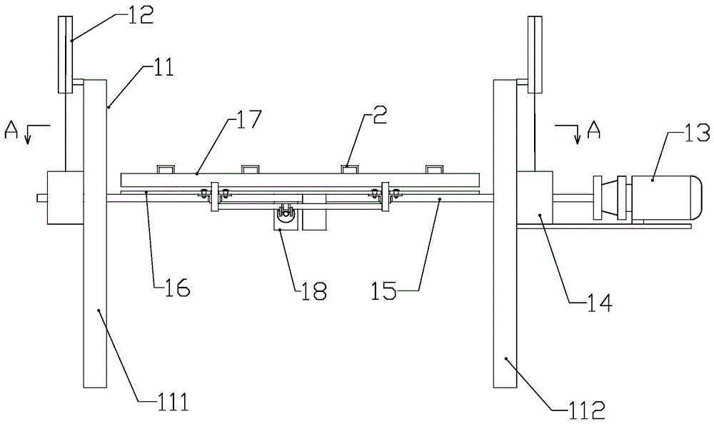
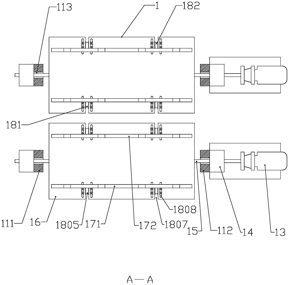
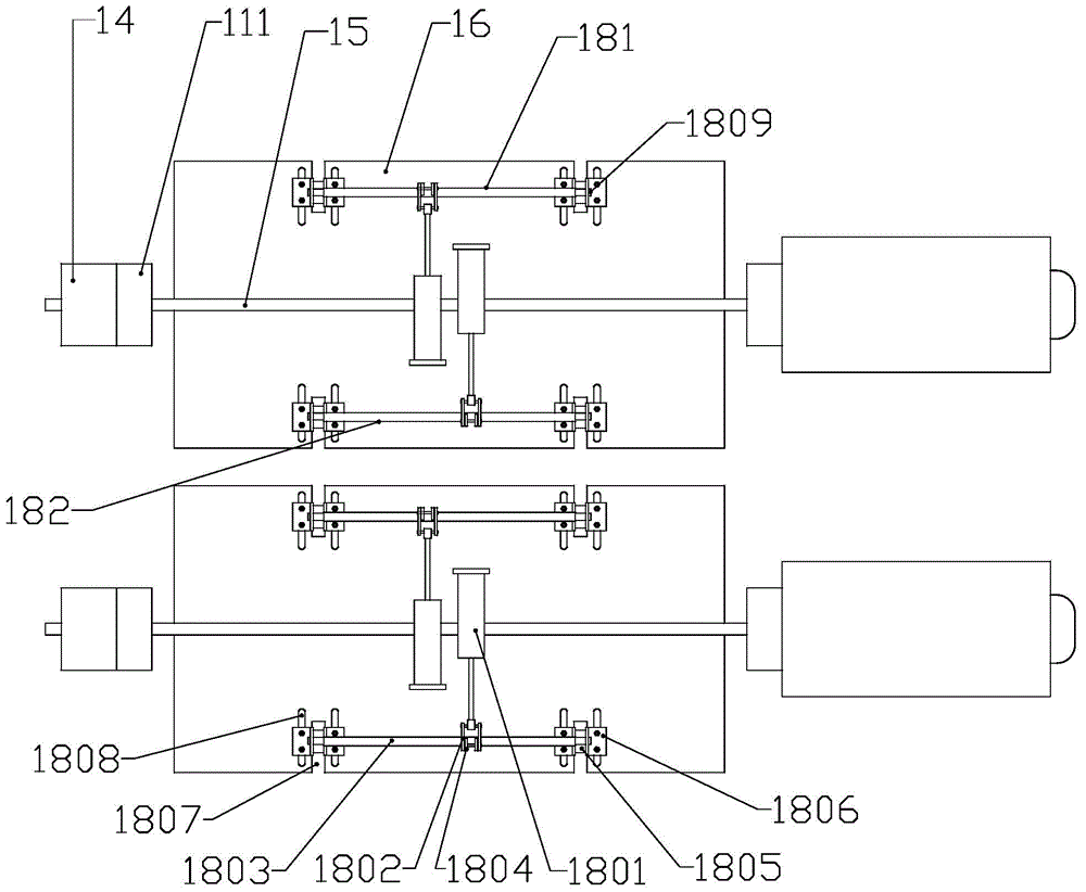
[0016] Refer to the attached figure 1 to attach Figure 4 The automatic component flipping demoulding machine of the present invention will be described in detail below.

[0017] The automatic component flipping demoulding machine of the present invention, its structure comprises two sets of flipping demoulding mechanisms 1, described two sets of flipping demoulding mechanisms 1 are arranged front and rear, and each set of flipping demoulding mechanisms 1 includes support 11, moves up and down Cylinder 12, overturning motor 13, slide block 14, rotating shaft 15, overturning plate 16, mold fixing clamping plate 17 and clamping plate moving drive mechanism 18, described support 11 comprises left support 111 and right support 112, described left support 111 and Right support 112 is respectively arranged on the left and right sides of turnover plate 16, and the outer side of described left support 111 and right support 112 is respectively provided with up and down moving cylinder...


PUM


Abstract

The invention discloses an automatic component overturning demolding machine, and belongs to demolding machines. The automatic component overturning demolding machine structurally comprises two sets of overturning demolding mechanisms. Each set of overturning demolding mechanism comprises a support, upper-down moving cylinders, an overturning motor, sliding blocks, a rotating shaft, an overturning plate, a mold fixed clamping plate and a clamping plate movable driving mechanism. Each support comprises a left support body and a right support body, the outer side of the left support body and the outer side of the right support body are respectively provided with one upper-down moving cylinder, and cylinder rods of the upper-down moving cylinders are connected with the sliding blocks respectively. One rotating shaft is arranged between the sliding block on the outer side of each left support body and the sliding block on the outer side of the corresponding right support body, each rotating shaft is movably connected with the two corresponding sliding blocks, and one end of each rotating shaft is connected with a motor shaft of the corresponding overturning motor. Each overturning plate is arranged on the upper portion of the corresponding rotating shaft, each mold fixed clamping plate is arranged on the upper portion of the corresponding overturning plate, and each mold fixed clamping plate is connected with the corresponding clamping plate movable driving mechanism. The automatic component overturning demolding machine has the advantages that mechanical automation is achieved in component demolding, manual operation is avoided, time and labor are saved, the labor intensity of workers is lowered, the mechanical action is simple, and the working efficiency is high.

Description

technical field [0001] The invention relates to a demoulding machine, in particular to an automatic component flipping demoulding machine used in a small concrete component production line. Background technique [0002] Small plastic concrete components are still produced by manual pouring, which has low production efficiency and cannot meet the short-term and large-scale procurement needs. In the manual pouring production process, when the components need to be demolded, the mold with the components is usually lifted manually, then the mold is manually turned over, and then manually touched to the ground to knock out the components in the mold, which is not only time-consuming and laborious, but also increases It reduces the labor intensity of workers and reduces production efficiency. [0003] Currently, there is no good solution. Contents of the invention [0004] The technical task of the present invention is to provide an automatic component flipping demoulding mach...

Claims


Application Information

Patent Timeline
Patent Type & Authority Applications(China)
IPC IPC(8): B28B13/06
CPCB28B13/06
Inventor 陈红卫
Owner JINAN DONGYUAN CEMENT PROD CO LTD
Learn More