Injection compression molding composite mould

A compound mold and compression molding technology, which is applied in the field of injection compression molding technology, can solve the problems of high technology content, high cost of mechanical equipment design and manufacturing, and achieve the goal of expanding the application range, easy automation, and accurate temperature control Effect

Inactive Publication Date: 2014-11-19
TIANJIN UNIVERSITY OF TECHNOLOGY
View PDF4 Cites 12 Cited by
  • Summary
  • Abstract
  • Description
  • Claims
  • Application Information

AI Technical Summary

Problems solved by technology

[0003] At present, various special injection machines have been continuously explored and developed, but due to their high technological content, the design and manufacturing costs of mechanical equipment are too high to be widely used.

Method used


Image

  • Injection compression molding composite mould
  • Injection compression molding composite mould
  • Injection compression molding composite mould

Examples


Embodiment 1

[0020] Embodiment 1, a kind of injection compression composite mold

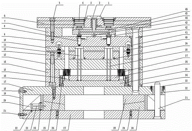
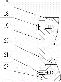
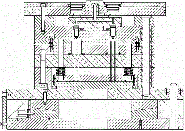
[0021] like figure 1 Shown, a composite mold for injection compression molding. The hot runner plate 45 is suspended in the backing plate frame 7. There is a fixed mold seat plate 6 on the top and a fixed template 9 on the bottom. The driving hydraulic cylinder 4 on the fixed mold seat plate is used to drive the switch pin 46 on the runner plate and the nozzle. 8 movement, and then to open and close the gate. The axis lines of the injection points of the fixed mold seat plate 6, the hot runner plate 45 and the fixed template 9 have been aligned, which ensures that the switch pin can move freely. A central positioning pin 44 is arranged on the central axis of the runner plate and the fixed template, and two anti-rotation positioning pins 43 are arranged on the upper and lower diagonal corners of the runner plate, and the two jointly locate the position of the runner plate. The compression movement of the c...


PUM


Abstract

The invention provides an injection compression molding composite mould. On the basis of a common valve type hot runner injection mould, a compression gap is reserved between a cavity plate and a core insert fixing plate; a slide block is pushed by a compression hydraulic cylinder mounted on a movable mould seat plate to slide horizontally on the movable mould seat plate; the horizontal movement is converted into movement vertical to mould splitting surfaces of other parts except the cavity plate, namely a fixed slide block, a pressure plate and a movable mould side through a contacted surface of a movable slide block and the fixed slide block; and finally, movement relative to the reserved compression gap is formed between a core insert and the cavity plate. A common injection molding machine does not have a secondary mould closing function and the composite mould can realize an injection compression molding process on the common injection molding machine, so that the precision of a product is improved on the basis of existing equipment and control system, and the application range of the common injection molding machine is enlarged.

Description

technical field [0001] The invention relates to the realization of an injection compression molding process on a common injection molding machine. Specifically, when the injection machine itself does not have a compression function, after the mold is clamped once under the action of the main mold clamping force of the equipment, the movable mold side continues to move relative to the fixed mold side through the mold’s own compression mechanism Perform secondary mold compression to obtain the final shape of the workpiece. Background technique [0002] With the development of injection molding technology, people's requirements for rubber and plastic parts are getting higher and higher, and the traditional injection molding process can no longer meet the requirements of high-precision product molding. As an advanced molding technology and an effective method for molding precision rubber and plastic products, injection compression molding technology is being adopted more and m...

Claims


Application Information

Patent Timeline
Patent Type & Authority Applications(China)
IPC IPC(8): B29C45/26B29C33/30
CPCB29C45/56B29C2045/5635B29C2045/5645B29C2045/565
Inventor 宋继顺刘倩倩王华龙张珍王卫东陈江平
Owner TIANJIN UNIVERSITY OF TECHNOLOGY
Why Eureka
Try Eureka