Pipeline conveying block preventing equipment under pressure feed state and using method thereof

An anti-clogging equipment and pipeline transportation technology, applied in the field of pipelines, can solve problems such as troublesome disassembly, cleaning and installation, limited effect of purging methods, and threats to product quality, so as to achieve high practical value, avoid unsafe conditions, and eliminate blockages short time effect

Active Publication Date: 2014-11-19
KAWATA MASCH MFG (SHANGHAI) CO LTD
View PDF5 Cites 2 Cited by
  • Summary
  • Abstract
  • Description
  • Claims
  • Application Information

AI Technical Summary

Problems solved by technology

Since the conventional pipelines are installed at high altitude, it is very troublesome to disassemble, clean and install, and there are potential safety hazards. The whole process takes a long time, which affects the production progress.
If you don’t clean the materials in the pipeline, it is easy to face the situation of being forced to shut down. In severe cases, it is necessary to arrange special personnel to clean up continuously, or even cut the pipeline to deal with it
Not only affects the output, but also threatens the product quality
If left alone, the final situation may cause production accidents, resulting in unpredictable and serious consequences
Although the blockage can be removed by purging, the effect of purging is very limited because it is in the state of pressure feeding and the entire pipeline is isolated from the atmosphere.

Method used


Image

  • Pipeline conveying block preventing equipment under pressure feed state and using method thereof
  • Pipeline conveying block preventing equipment under pressure feed state and using method thereof
  • Pipeline conveying block preventing equipment under pressure feed state and using method thereof

Examples


Embodiment Construction

[0064] In order to understand the technical content of the present invention more clearly, the specific implementation method of the present invention will be further described below in conjunction with the accompanying drawings.

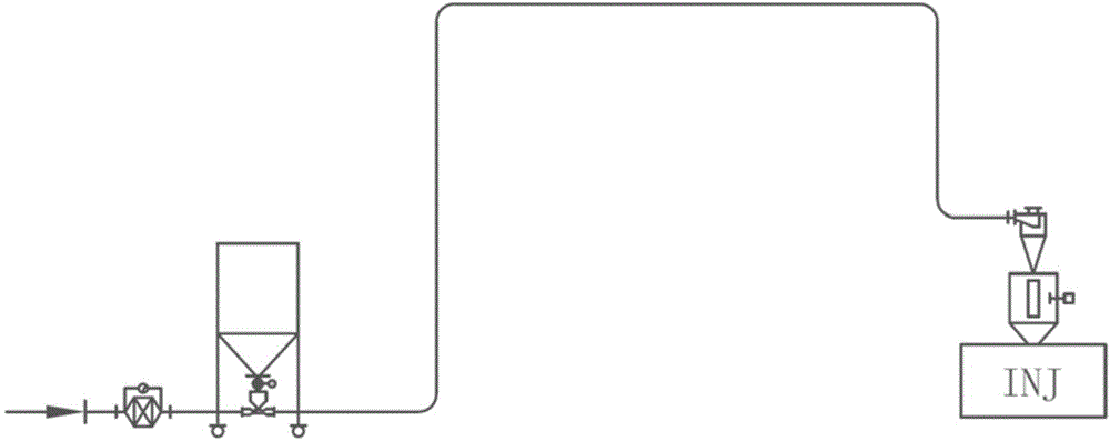
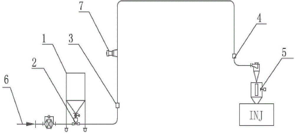
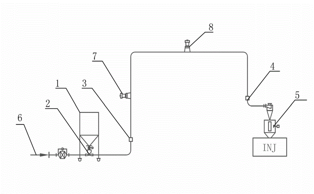
[0065] Figure 2a-2c They are the schematic diagrams of the anti-clogging equipment for pipeline transportation under the pressure feeding state of the three embodiments of the present invention, wherein, the first embodiment has one vibrator, the second embodiment has two vibrators, and the third embodiment The example has three vibrators. Such as Figure 2a-2c As shown, the anti-clogging equipment for pipeline transportation under the pressure feeding state includes:

[0066] The conveying pipeline part, at least two detection devices and at least one vibrating device both arranged on the conveying pipeline part;

[0067] Wherein, the conveying pipeline part includes a pipeline, a conveying hopper 5, a conveying valve 2 and an air inlet 6 conne...


PUM


Abstract

The invention relates to pipeline conveying block preventing equipment under a pressure feed state. The pipeline conveying block preventing equipment under the pressure feed state is characterized by comprising a conveying pipe part, at least two detection devices and at least one vibration device, wherein the at least two detection devices and the at least one vibration device are all arranged on the conveying pipe part. The conveying pipe part comprises a pipeline, a conveying hopper, a conveying valve, a charging barrel and an air inlet connected with the conveying valve. One end of the pipeline is connected with the charging barrel through the conveying valve, the other end of the pipeline is connected with the conveying hopper, the at least two detection devices and the at least one vibration device are arranged on the pipeline, and the at least one vibration device is located between the at least two detection devices. By the adoption of the pipeline conveying block preventing equipment under the pressure feed state, pipeline blocking can be detected automatically, the pipeline blocking can be processed automatically in a vibration mode, manpower and material resources are saved, and the production progress of clients cannot be influenced.

Description

technical field [0001] The invention relates to the field of pipelines, in particular to pipeline cleaning and anti-blocking equipment, in particular to an anti-clogging equipment for pipeline transportation in a pressure-feeding state and a method for using the same. Background technique [0002] The pipeline conveying device in the pressure-feeding state in the existing plastic auxiliary machinery industry does not have the function of detecting and dealing with pipeline blockage, such as figure 1 The secondary delivery of the material shown (transportation from the storage device to the molding machine side), due to material agglomeration, impurities in the material, etc., causes the material to form a blockage in the delivery pipe. Under normal circumstances, the pipelines for secondary transportation are long, and it is difficult to find the blockage in the first place. It is often only after the molding machine is short of material that the alarm is issued that the pi...

Claims


Application Information

Patent Timeline
Patent Type & Authority Applications(China)
IPC IPC(8): B65G53/66
Inventor 中村文三郎鲍观寅高雷
Owner KAWATA MASCH MFG (SHANGHAI) CO LTD
Why Eureka
Try Eureka