
Ultra-extensive micro-bubble air-flotation machine

An air flotation machine and micro-bubble technology, which is used in flotation water/sewage treatment and other directions, can solve the problems of complex operation, large equipment footprint, and reduced processing capacity, and achieves simple operation and debugging, small footprint, and increased production capacity. High throughput effect

Inactive Publication Date: 2014-11-19
台东蛟
View PDF0 Cites 2 Cited by
  • Summary
  • Abstract
  • Description
  • Claims
  • Application Information

AI Technical Summary

Problems solved by technology

The main disadvantages of the existing air flotation equipment are: 1. The air-dissolving device is an independent unit. It needs to use a high-pressure pump to pump the water treated by the air flotation machine back to dissolve the air, and then inject it into the system after it is dissolved.
Not only wasting power, but also greatly reducing the processing capacity
2. Since the traditional air-dissolving device injects high-pressure air directly into high-pressure water, controlling the gas-liquid ratio has become a key issue. A slight improper operation will cause the air flotation effect to be unstable and the water to come out unclear. , the operation is complicated and requires very professional personnel to operate
3. The air flotation box is divided into two independent areas: the contact area and the separation area. If the separation time is too long, the box will be too large and the equipment will occupy too much area.
4. The discharge of scum in traditional air flotation equipment is realized through a special scraper mechanism, which not only increases the hidden danger of failure and the probability of maintenance, but also causes a waste of power for the scraper
5. During the use of traditional air flotation equipment, a large amount of sediment will be generated at the bottom of the tank, which requires regular shutdown to manually clean the sediment, which is labor-intensive

Method used


Image

  • Ultra-extensive micro-bubble air-flotation machine

Examples


Embodiment Construction

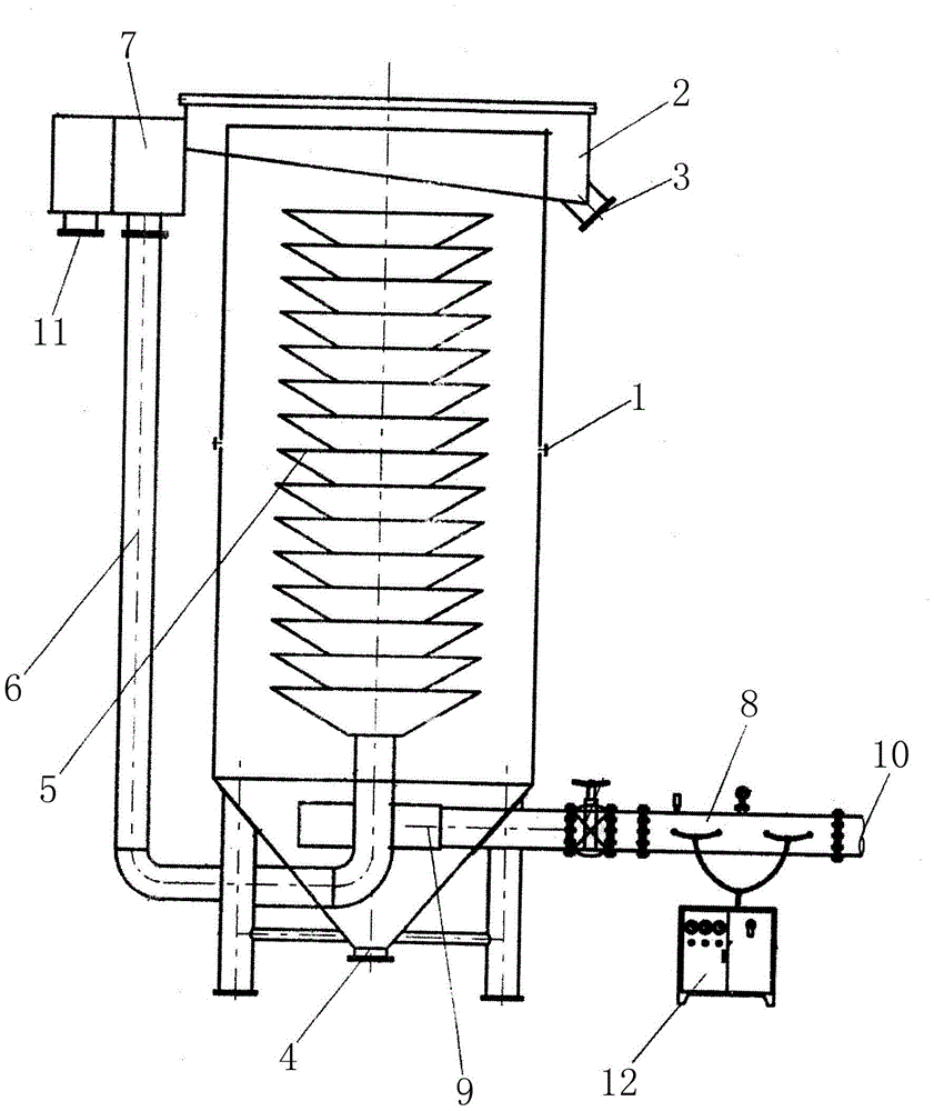
[0009] Such as figure 1 As shown, the present invention is equipped with a scum collection tank 2 on the top of the tank body 1, and a scum discharge pipe 3 is provided at the bottom of one side of the scum collection tank 2, the bottom of the tank body 1 is conical, and the sludge discharge port 4 is located at the bottom of the tank body 1, and a group of inverted cone-shaped diversion water-collecting pieces 5 are arranged in the inner middle of the tank body 1. The upper tank 7 on one side of the body 1 is connected, the gas dissolving device 8 is arranged on the other side of the tank body 1, and the gas dissolving device 8 is connected with the water distribution device 9 arranged at the inner bottom of the tank body 1 through a pipeline. The bottom of the scum collecting tank 2 is inclined.

[0010] Through the above settings, sewage enters the air-dissolving device 8 through the water inlet 10 of the present invention, enters the high-pressure air of the air-dissolvin...


PUM


Abstract

The invention discloses an ultra-extensive micro-bubble air-flotation machine which is characterized in that a dross collecting tank is mounted on the top of a tank body; a dross discharge tube is arranged at the bottom of one side of the dross collecting tank; a sludge discharge hole is formed in the bottom of the tank body; a group of inverted conical flow guide water collection pieces are arranged in the middle inside the tank body; the bottoms of the inverted conical flow guide water collection pieces are connected with a high-level tank which is arranged at the upper part of one side of the tank body through a U-shaped clean water pipeline; an air dissolving device is arranged on the other side of the tank body; the air dissolving device is connected with a water distributor through a pipeline; the water distributor is arranged at the bottom inside the tank body. Due to the components, the ultra-extensive micro-bubble air-flotation machine is capable of dissolving air into sewage directly, the dross can be discharged by virtue of self-flowing, the sludge at the bottom of the tank body can be discharged automatically, and thus both the power is saved and the processing amount is increased. The ultra-extensive micro-bubble air-flotation machine is small in occupied space, simple to operate and debug and high in air-flotation efficiency.

Description

technical field [0001] The invention relates to an air flotation device in the field of sewage treatment, in particular to a super-efficient microbubble air flotation machine. Background technique [0002] The existing air flotation equipment used for sewage treatment is mainly composed of an independent dissolved air device and an air flotation machine box. The air flotation return water passes through the high-pressure pump and the high-pressure air generated by the air compressor is mixed in the independent pressure vessel device to form dissolved air. water, and then enter the separation zone for separation. The main disadvantages of the existing air flotation equipment are: 1. The air dissolving device is an independent unit, and it is necessary to use a high-pressure pump to pump back the water treated by the air flotation machine for dissolving the air, and then inject it into the system after dissolving. Not only wasting power, but also greatly reducing the processi...

Claims


Application Information

Patent Timeline
Patent Type & Authority Applications(China)
IPC IPC(8): C02F1/24
Inventor 台东蛟
Owner 台东蛟
Learn More