Concrete pile construction equipment and method

A technology for concrete piles and construction devices, which is applied to sheet pile walls, infrastructure engineering, construction, etc., can solve the problems of difficulty in forming the design depth of the pile holes, not making full use of the original soil, and unable to carry out the next construction. Fast, wide-ranging, robust results

Active Publication Date: 2014-11-19
北京波森特岩土工程有限公司
View PDF7 Cites 3 Cited by
  • Summary
  • Abstract
  • Description
  • Claims
  • Application Information

AI Technical Summary

Problems solved by technology

This geological condition makes it very difficult to form holes in the pile body during pile foundation construction. At present, the commonly used methods such as vibration sinking, static pressure or rotary drilling are basically difficult to form pile holes to the design depth.
Although rotary drilling rigs and manual digging can form holes in relatively hard soil layers, they are both methods of taking out the original soil. Not only do they need to clear the soil and transport it outside, resulting in increased costs and environmental pollution, but also because the original soil and soil are not fully utilized. Without the retaining wall, it is very easy to cause the hole wall to collapse and shrink, especially when the groundwater content is high, the pile hole will be flooded with water quickly, and the next step of construction cannot be carried out

Method used


Image

  • Concrete pile construction equipment and method
  • Concrete pile construction equipment and method
  • Concrete pile construction equipment and method

Examples


Embodiment Construction

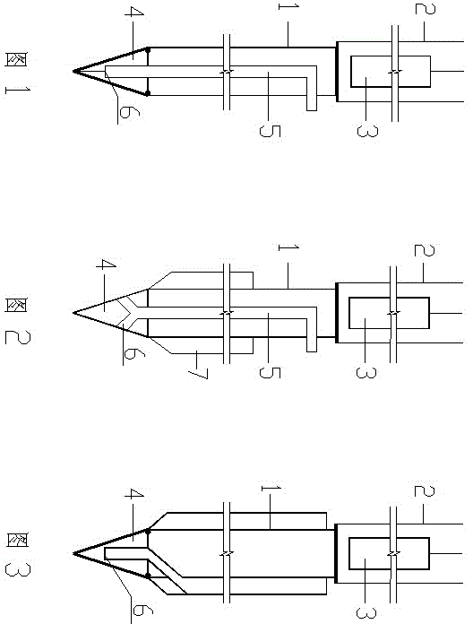
[0057] figure 1 It is the sectional view of an embodiment of the construction device of the concrete pile of the first kind of structural form of the present invention, as figure 1 As shown, the top of the casing 1 is connected and fixed with a ramming sleeve 2, and a ramming hammer that can be lifted is arranged inside the ramming sleeve 2; the bottom end of the casing 1 is connected and fixed with an impact hammer tip 4, and the impact hammer tip 4 consists of four Composed of three triangular steel plates, the upper side of each steel plate is hingedly connected with the bottom end of the casing 1 for easy closing and opening. When the steel plates are closed inward, a hollow cone with a sharp point downward is formed, and an opening is formed when the steel plate is opened outward; The interior of the casing 1 is provided with a delivery pipe 5 capable of transporting concrete. The upper opening of the delivery pipe 5 protrudes out of the casing 1 at the upper end of the c...


PUM


Abstract

The invention aims to provide concrete pile construction equipment comprising a guard cylinder which is round, a tamp sleeve, a tamper, a delivery pipe, and an impact peen. The concrete pile construction equipment has two structural modes I and II. The concrete pile construction equipment is characterize in that in the structural mode I, the tamp sleeve and the tamper are disposed at the top end of the guard cylinder, the impact peen is disposed at the bottom end of the guard cylinder, the delivery pipe is disposed inside the guard cylinder, the impact peen is provided with a discharge opening, and an additional part is added to the outside of the guard cylinder to obtain a special-shaped guard cylinder; in the structural mode II, two cylinder tamping manners are used, the impact peen is disposed at the bottom end of the guard cylinder, a plurality of steel pipes or U-shaped pipes, one of which is the delivery pipe, are arranged on the outer wall of the guard cylinder, and the impact peen is provided with a discharge opening . The invention further provides a construction method employing the concrete pile construction equipment. The method includes the steps of 1, aligning a pile position; 2, hammering the tamp sleeve to obtain a pile hole; 3, stopping hammering until the guard cylinder sinks to a designed depth; 4, lifting up the guard cylinder while delivering concrete into the delivery pipe; 5, stopping lifting until the guard cylinder is completely out; 6, performing following construction.

Description

technical field [0001] The utility model relates to the field of civil engineering, in particular to the construction technology of piles. Background technique [0002] In the foundation treatment of buildings, it is often encountered that there are dense sandy soil layers, gravel soil layers, loess layers, gravel and pebble layers, etc. at a certain depth below the surface, and the hardness of these soil layers is uneven. , Uneven thickness. This geological condition makes it very difficult to form holes in the pile body during pile foundation construction. At present, it is difficult to form pile holes to the designed depth with the commonly used methods such as vibratory sinking, static pressure or rotary drilling. Although rotary drilling rigs and manual digging can form holes in relatively hard soil layers, they are both methods of taking out the original soil. Not only does it need to clear the soil and transport it outside, resulting in increased costs and environmen...

Claims


Application Information

Patent Timeline
Patent Type & Authority Applications(China)
IPC IPC(8): E02D5/38E02D7/28
Inventor 王继忠
Owner 北京波森特岩土工程有限公司
Why Eureka
Try Eureka