Steel pipe concrete jacking inserting plate type control device and method for connecting steel pipe concrete jacking inserting plate type control device to steel pipe column

A technology of control device and connection method, which is applied in the direction of construction and building construction, can solve the problems of inconvenient installation and dismantling, difficulty in device manufacturing, high sealing requirements, etc., and achieve the effect of eliminating welding process, convenient assembly and disassembly, and low cost

Inactive Publication Date: 2014-11-19
MCC TIANGONG GROUP
View PDF0 Cites 3 Cited by
  • Summary
  • Abstract
  • Description
  • Claims
  • Application Information

AI Technical Summary

Problems solved by technology

When such a device is connected, it is necessary to weld elbows on each steel pipe column. The amount of elbows is large, and a shut-off valve needs to be installed on each elbow, and the sealing requirements are also high. It has defects such as difficulty in device manufacture, inconvenient installation and dismantling, and high cost of use.

Method used


Image

  • Steel pipe concrete jacking inserting plate type control device and method for connecting steel pipe concrete jacking inserting plate type control device to steel pipe column
  • Steel pipe concrete jacking inserting plate type control device and method for connecting steel pipe concrete jacking inserting plate type control device to steel pipe column
  • Steel pipe concrete jacking inserting plate type control device and method for connecting steel pipe concrete jacking inserting plate type control device to steel pipe column

Examples


Embodiment Construction

[0029] Specific embodiments of the present invention will be described in detail below in conjunction with the accompanying drawings.

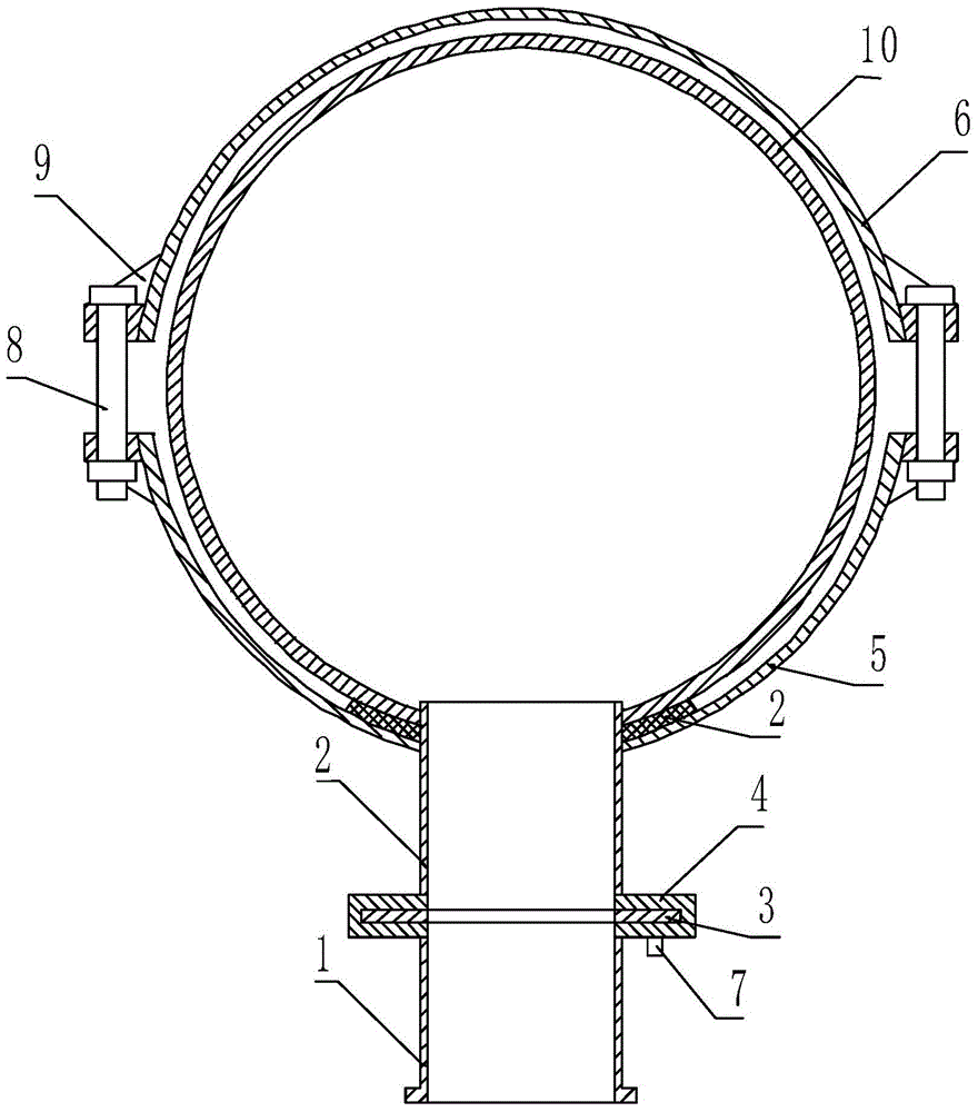
[0030] A steel pipe concrete jacking plate type control device, such as figure 2 As shown, it includes pumping pipe 1, feeding pipe 2, inserting plate 3, inserting plate box 4, front hoop 5 and rear hoop 6; one end of the feeding pipe 2 passes through and is welded on the front hoop 5 , the other end is welded on the cardboard box 4; the side of the cardboard box 4 different from the feed pipe 2 is welded to the pumping pipe 1; the cardboard 3 is fixed in the cardboard box 4 by a latch 7; The rear hoop 6 is connected with the front hoop 5 through a connecting piece 8 . The connection 8 may preferably be bolts. Wherein, the inner diameters of the pumping pipe 1 and the feeding pipe 2 which are arranged correspondingly are the same.

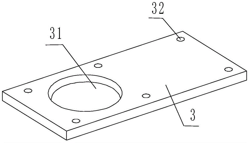
[0031] Among them, such as Figure 4 As shown, the middle part of the cardboard box 4 is provided with a ca...


PUM


Abstract

The invention provides a steel pipe concrete jacking inserting plate type control device and a method for connecting the steel pipe concrete jacking inserting plate type control device to a steel pipe column. The steel pipe concrete jacking inserting plate type control device comprises a pumping pipe, a feeding pipe, an inserting plate, an inserting plate box, a front hoop and a rear hoop, wherein one end of the feeding pipe penetrates through and is welded to the front hoop, the other end of the feeding pipe is welded to the inserting plate box, the side, opposite to the feeding pipe, of the inserting plate box is welded to the pumping pipe, and the inserting plate is fixed into the inserting plate box through an inserting pin; the rear hoop is connected with the front hoop through a connector, a cavity is formed in the inserting plate box, the pumping pipe and the feeding pipe are both communicated with the cavity and are welded to the two sides of the inserting plate box coaxially, and the inserting plate inserted in the cavity controls on or off of concrete flow between the pumping pipe and the feeding pipe. When the steel pipe concrete jacking inserting plate type control device is connected to the steel pipe column, whether the wall thickness of each pipe meets the requirements or not is checked, then cleaning work is carried out, and installation is carried out finally. The steel pipe concrete jacking inserting plate type control device is low in manufacturing cost, can effectively connect a steel pipe to a concrete pump pipe together and can control concrete poured into the steel column to flow out. Meanwhile, the connecting method is simple, is feasible and enables detachment to be convenient.

Description

technical field [0001] The invention belongs to the technical field of steel pipe concrete jacking, and in particular relates to a steel pipe concrete jacking plate control device and a connection method with a steel pipe column. Background technique [0002] In the construction of the steel pipe column concrete jacking of the steel structure factory building, compared with the defects of the high throw steel structure concrete construction process and construction equipment, etc., the jacking concrete construction is to open a temporary pouring hole at the lower part of the steel pipe column, and use a concrete pump to lift the concrete from the bottom. The upper pouring of concrete can effectively avoid the phenomenon of concrete incompactness and segregation, and ensure that the concrete meets the quality requirements. In addition, since there is no need to erect high-altitude scaffolding, it reduces the amount of high-altitude operations and has high safety, so it is wide...

Claims


Application Information

Patent Timeline
Patent Type & Authority Applications(China)
IPC IPC(8): E04B1/35
Inventor 徐岐亮
Owner MCC TIANGONG GROUP
Why Eureka
Try Eureka