Split type oil spray nozzle of diesel engine
A split-type, fuel-injector technology, applied in mechanical equipment, engine components, machines/engines, etc., can solve the problems of increased maintenance costs, low spray opening pressure and atomization level, and large impact force of the fuel injector. Improve the efficiency of use, increase the opening pressure of the spray, and reduce the impact of sports
Inactive Publication Date: 2014-11-19
YANGZHOU HONGTU MACHINERY MFG
View PDF0 Cites 0 Cited by
- Summary
- Abstract
- Description
- Claims
- Application Information
AI Technical Summary
Problems solved by technology
[0002] At present, the fuel injectors used on diesel engines generally include a valve body and a valve needle arranged in the valve body. The valve body is generally used as an integral structure and has many defects: on the one hand, if there is damage, it needs to be replaced as a whole, which increases maintenance. Cost; on the other hand, the impact force of the fuel injector during operation is relatively large, and the spray opening pressure and atomization level are low
Method used
View moreImage
Smart ImageViewing Examples

Examples
Embodiment Construction
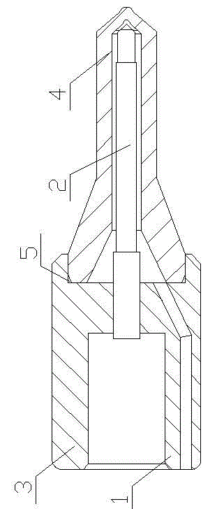
[0007] Such as figure 1 As shown, the present invention includes a valve body 1 and a needle valve 2 arranged in the valve body 1. The valve body 1 includes a transition body 3 and a nozzle 4. The center of the right end of the transition body 3 is provided with a card slot 5. One end of the nozzle 4 The card is placed in the card slot 5 at the right end of the transition body 3 .
Login to View More PUM
 Abstract
The invention provides a split type oil spray nozzle of a diesel engine, and relates to the field of diesel engine components. The split type oil spray nozzle of the diesel engine comprises a valve body and a needle valve arranged in the valve body and is characterized in that the valve body comprises a transition body and an oil nozzle, the center at the right end of the transition body is provided with a clamping groove, and one end of the oil nozzle is arranged in the clamping groove in the right end of the transition body in a clamped mode. The split type oil spray nozzle of the diesel engine is convenient to maintain, work inertia of the oil spray nozzle is reduced, motion impact force is reduced, the spray opening pressure is increased, diesel fuel atomization is made to be fine and even, burning is conducted evenly in an air cylinder, emission is lowered, the fuel efficiency is improved, and the use efficiency of a product is improved.
Description
technical field [0001] The invention relates to the field of diesel engine components, in particular to a diesel engine split fuel injector. Background technique [0002] At present, the fuel injectors used on diesel engines generally include a valve body and a valve needle arranged in the valve body. The valve body is generally used as an integral structure and has many defects: on the one hand, if there is damage, it needs to be replaced as a whole, which increases maintenance. Cost; on the other hand, the impact force of the fuel injector during operation is relatively large, and the spray opening pressure and atomization level are low. Contents of the invention [0003] The purpose of the present invention is to provide a diesel engine split fuel injector with small working impact force, convenient maintenance and good atomization level. [0004] The technical solution to achieve the above purpose is: split fuel injector for diesel engine, including a valve body and a...
Claims
Login to View More Application Information
Patent Timeline
 IPC IPC(8): F02M61/10
Inventor 王波
Owner YANGZHOU HONGTU MACHINERY MFG