Integrated bearing seat

A technology of bearing seat and bearing hole, which is applied in the direction of bearing components, shafts and bearings, rigid supports of bearing components, etc., which can solve the problems of uncompact structure and inability to ensure the accuracy of bearing connection

Inactive Publication Date: 2014-11-19
扬中市金德纺织机械设备厂
View PDF6 Cites 3 Cited by
  • Summary
  • Abstract
  • Description
  • Claims
  • Application Information

AI Technical Summary

Problems solved by technology

This method, one is that the structure is not compact, and the other i

Method used


Image

  • Integrated bearing seat
  • Integrated bearing seat

Examples


Embodiment Construction

[0015] The design will be further described below in conjunction with the accompanying drawings of the description.

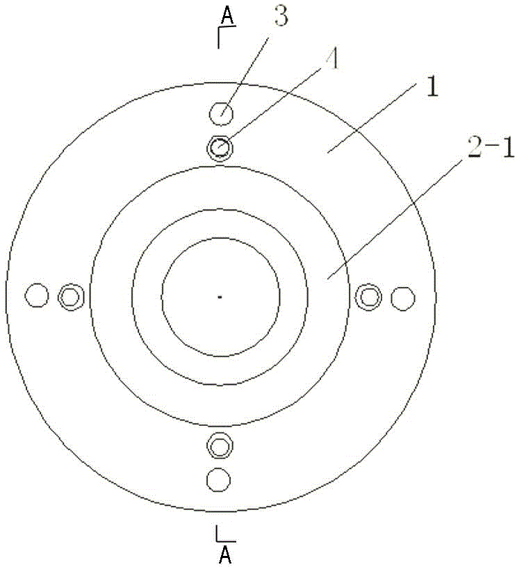
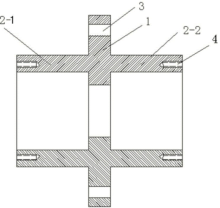
[0016] like figure 1 , 2 As shown, an integrated bearing seat is characterized in that it includes a flange plate 1, a left bearing seat 2-1, and a right bearing seat 2-2. Bolt holes 3 are evenly distributed on the flange plate 1, and the left bearing Seat 2-1, right bearing seat 2-2 are provided with screw hole 4.

[0017] The bolt holes 3 of the flange are used to fix the bearing seat, and the screw holes on the left bearing seat 2-1 and the right bearing seat 2-2 are used to connect the bearing cap.

[0018] Preferred:

[0019] The above-mentioned integrated bearing housing is characterized in that: the diameter of the bearing hole 4 of the left bearing housing 2-1 and the right bearing housing 2-2 is larger than the diameter of the flange hole of the flange plate 1 .

[0020] The flange hole of the flange is smaller than the bearing hole of the bearing ...


PUM


Abstract

The invention discloses an integrated bearing seat which is characterized by comprising a flange disc, a left bearing seat and a right bearing seat, wherein bolt holes are uniformly formed in the flange disc and screw holes are formed in both the left and right bearing seats. The invention aims at providing the integrated bearing seat, the two bearing seats are integrally manufactured; not only is the connecting method of the bearing seats simplified, and also the connecting accuracy of the two bearings is guaranteed and the integrated bearing seat is compact in structure.

Description

technical field [0001] The design relates to an integrated bearing seat, which belongs to the technical field of mechanical manufacturing. Background technique [0002] Two bearings in the existing textile machine are connected, and two bearing seats are generally adopted to install two bearings respectively, and then the two bearing seats are connected. This method, on the one hand, is not compact in structure, and on the other hand, cannot guarantee the connection accuracy of the two bearings. Contents of the invention [0003] Aiming at the deficiencies of the existing technology, the purpose of this design is to provide an integrated bearing seat. The two bearing seats are manufactured in an integrated manner, which not only simplifies the connection method of the two bearing seats, has a compact structure, but also ensures that the two bearing seats are connection accuracy. [0004] In order to achieve the above purpose, this design is realized through the follo...

Claims


Application Information

Patent Timeline
IPC IPC(8): F16C35/00
Inventor 陈德华黄文
Owner 扬中市金德纺织机械设备厂
Why Eureka
Try Eureka