Device for detecting telescope lens

A technology for detection devices and telescopes, which is applied in the direction of testing optical performance, etc., and can solve the problems of large volume, occupation, and the relative distance between the interferometer and the lens under test, etc.

Active Publication Date: 2014-11-19
NANTONG SCHMIDT OPTO ELECTRICAL TECH CO LTD
View PDF5 Cites 1 Cited by
  • Summary
  • Abstract
  • Description
  • Claims
  • Application Information

AI Technical Summary

Problems solved by technology

[0003] 1. When the traditional detection device detects the lens, the lens is erected and positioned with a cylindrical surface. Since the cylindrical surface is not the working surface of the telescope when it is in use, the processing accuracy is not high, and the surface is usually not parallel or the thickness to be measured. Inconsistency, when replacing other lenses under test, it is necessary to constantly adjust the focal length of the interferometer so that it coincides with the axis of the lens under test
[0004] 2. When the traditional detection device detects a lens with a large diameter or a large curvature (R value), due to the influence of the diameter of the interferometer itself, the light emitted by the interferometer needs to exceed the diameter of the measured lens, so the guiding interferometer and The lens to be tested is relatively far away. In addition, the lens with a larger curvature (R value) has a longer focal distance, and the lens and the focus of the interferometer coincide at a farther position, resulting in a longer track moving mechanism, which in turn leads to The detection device is larger in size and occupies more space
[0005] 3. The traditional detection device uses the air cushion platform to reduce the interference vibration of the interferometer, but the air cushion platform uses many accessories and is bulky

Method used


Image

  • Device for detecting telescope lens
  • Device for detecting telescope lens
  • Device for detecting telescope lens

Examples


Embodiment Construction

[0028] The technical solution in the embodiment will be specifically, clearly and completely described below in conjunction with the drawings in the embodiment.

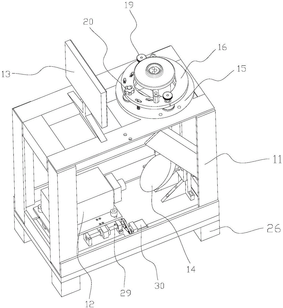
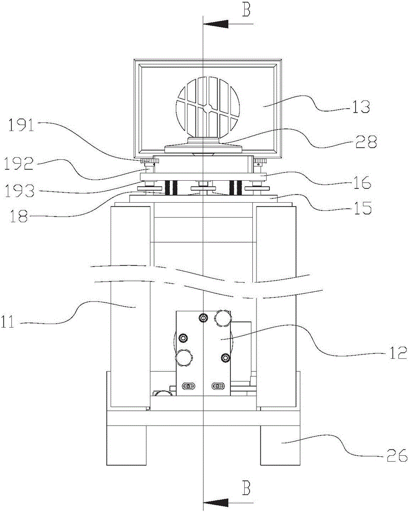
[0029] see Figure 2-6 Shown, a kind of telescope mirror inspection device comprises a workbench 11, an interferometer 12 located in the casing of the workbench 11 and a display 13 located on the table top of the workbench 11, and a The plane mirror 14 and the plane mirror collimation adjustment mechanism, the plane mirror 14 is located between the interferometer 12 and the plane mirror collimation adjustment mechanism, and the plane mirror 14 is obliquely connected with one side of the plane mirror collimation adjustment mechanism; Plate one 15, adjusting plate 16, positioning column 17, extension spring 18 and the image adjustment mechanism for adjusting the direction and thickness of the image line, the fixed plate one 15 is fixed on the table top, and the adjusting plate 16 is positioned at the top of the fixed p...


PUM


Abstract

The invention discloses a device for detecting a telescope lens. The device comprises a workbench, an interferometer arranged in a casing of the workbench and a display arranged on a table top of the workbench. The casing of the workbench is also internally provided with a flat mirror and a flat mirror collimation adjusting mechanism. The flat mirror is positioned between the interferometer and the flat mirror collimation adjusting mechanism. The flat mirror is connected with one side of the flat mirror collimation adjusting mechanism in an inclined manner. The table top of the workbench is provided with a fixing plate I, an adjusting plate, a positioning column, extension springs and an image adjusting mechanism, wherein the image adjusting mechanism is used for adjusting directions and thicknesses of image lines. The fixing plate I is fixed on the table top. The adjusting plate is above the fixing plate I and is connected with the fixing plate I through the extension springs. The positioning column is shaped like an inverted T and is fixedly arranged above the adjusting plate. The image adjusting mechanism is arranged on the adjusting plate, and a lower end part of the image adjusting mechanism is movably connected with the fixing plate I. The device provided by the invention is simple in structure, small in size and convenient to operate.

Description

technical field [0001] The invention relates to a lens detection device, in particular to a telescope lens detection device. Background technique [0002] A telescope is an optical instrument that uses lenses or mirrors and other optical devices to observe distant objects. The processing of telescope lenses usually needs to be ground on a grinding machine to ensure the accuracy and quality of the mirror. Such as figure 1 As shown, in order to ensure that the processing accuracy and quality of the telescope lens are within the acceptable range, it is usually necessary to use a detection device to detect the measured surface 281 (R surface) of the telescope lens 28, and the cylindrical surface 282 on the other side of the measured surface It is a non-working surface of the telescope, so no inspection is required. The traditional detection device mainly includes an interferometer, a lens positioning mechanism, a track moving mechanism for adjusting the position of the lens p...

Claims


Application Information

Patent Timeline
Patent Type & Authority Applications(China)
IPC IPC(8): G01M11/02
Inventor 沈达忠
Owner NANTONG SCHMIDT OPTO ELECTRICAL TECH CO LTD
Why Eureka
Try Eureka