Fan blade single side dynamic balancing machine

A dynamic balancing machine and fan blade technology, applied in static/dynamic balance testing, machine/structural component testing, measuring devices, etc., can solve problems such as reducing quality, affecting the accuracy of fan blade dynamic balancing testing, and increasing production costs.

Pending Publication Date: 2017-10-27
东莞市卓茂仪器有限公司
View PDF7 Cites 1 Cited by
  • Summary
  • Abstract
  • Description
  • Claims
  • Application Information

AI Technical Summary

Problems solved by technology

[0004] Different types of fan blades must be installed with different matching stator motors, which is time-consuming and troublesome to replace, and increases production costs; 2. The imbalance of the stator motor itself will affect the unbalance of the fan blades, increasing errors and reducing quality; 3. Manual adjustment is required The output of the power supply voltage is used to achieve the required speed of the test, and the efficiency is low. Some fan blades have no star spots or the star spots are not polished enough. It is necessary to paste photosensitive paper to detect the speed, which affects production efficiency, and the quality of the photosensitive paper itself will directly affect the fan blades. 4. The structure of the existing fan blade dynamic balancing machine is unstable. With the increase of the test volume, the error will continue to accumulate, thus affecting the test accuracy of the fan blade dynamic balance

Method used


Image

  • Fan blade single side dynamic balancing machine
  • Fan blade single side dynamic balancing machine
  • Fan blade single side dynamic balancing machine

Examples


Embodiment Construction

[0026] The present invention will be described in detail below in conjunction with the accompanying drawings.

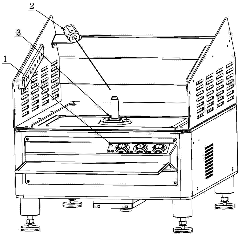
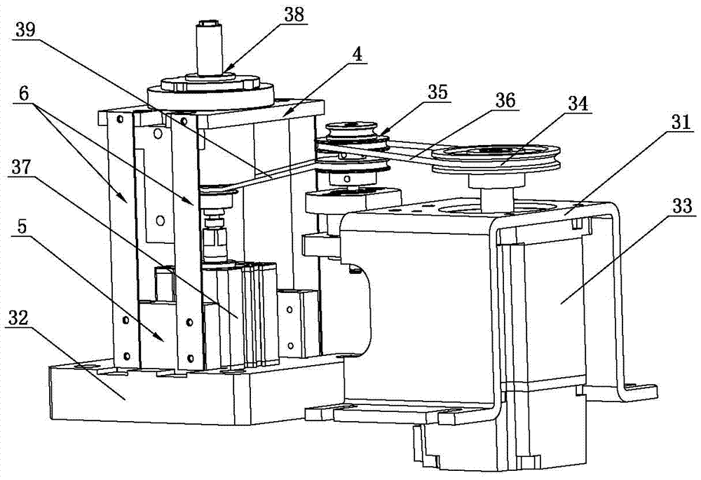
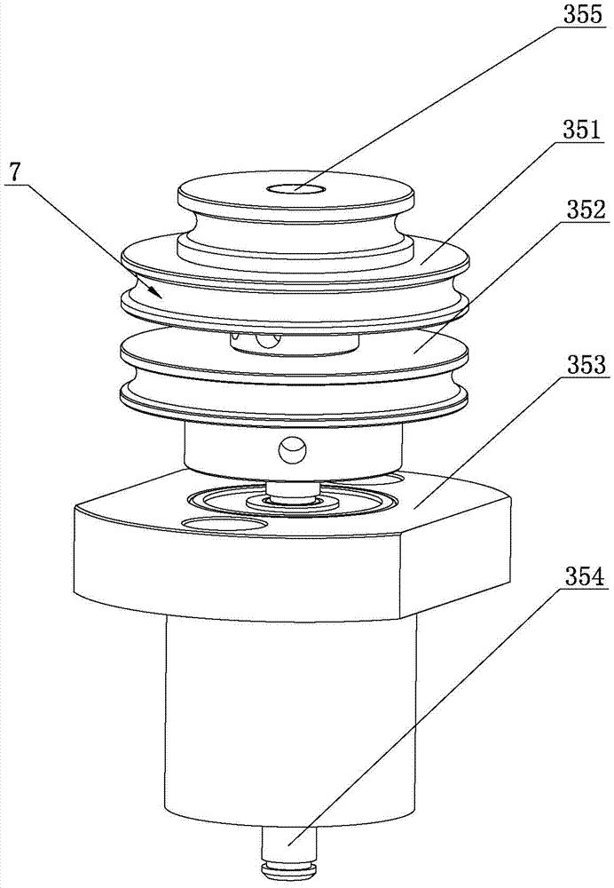
[0027] Such as Figure 1 to Figure 4 As shown, a fan blade single-sided dynamic balancing machine of the present invention includes a manipulation platform 1, a laser 2 is arranged on one side of the manipulation platform 1, and a fan blade servo transmission mechanism 3 is arranged on the side of the laser 2, The fan blade servo transmission mechanism 3 includes a frame 31 and a base 32. A servo motor 33 is arranged inside the frame 31. The output shaft of the servo motor 33 passes through the frame 31 and is connected to a rotating disc 34. The machine One side of the frame 31 is equipped with a transmission assembly 35, the rotating disc 34 is connected to the transmission assembly 35 through the first transmission belt 36, the base 32 is provided with a jacking cylinder 37, and the output shaft of the jacking cylinder 37 is connected to There are jaws 38 for ins...


PUM


Abstract

The invention relates to the technical field of a fan blade vibration quantity test device, in particular to a fan blade single side dynamic balancing machine. The fan blade single side dynamic balancing machine comprises an operation and control platform, wherein a laser is arranged at one side of the operation and control platform; a fan blade servo transmission mechanism is arranged beside the laser; the fan blade servo transmission mechanism comprises a machine frame and a base; a servo motor is arranged at the inner side of the machine frame; an output shaft of the servo motor passes through the machine frame to be connected with a rotating disc; a transmission assembly is arranged at one side of the machine frame; the rotating disc and the transmission assembly are in transmission connection through a first transmission belt; the base is provided with a jacking air cylinder; an output shaft of the jacking air cylinder is connected with a clamping jaw used for installing a fan blade; the transmission assembly is in transmission connection with the clamping jaw through a second transmission belt; the clamping jaw is arranged at an installing plate; an installing block is arranged under the installing plate; a support plate is connected between the installing plate and the installing block. The servo motor and the clamping jaw are matched for driving the fan blade to rotate; different work requirements are met; the fan blade detection precision and the fan blade detection efficiency are improved; the production quality of the fan blade is improved.

Description

technical field [0001] The invention relates to the technical field of devices for testing the vibration of fan blades, in particular to a single-sided dynamic balancing machine for fan blades. Background technique [0002] A dynamic balancing machine is a machine that measures the size and position of the unbalance of the fan blades of the product. As the fan blade rotates around its axis, centrifugal force is generated due to the uneven distribution of mass relative to the axis. This unbalanced centrifugal force will cause vibration on the blade bearing, generate noise and accelerate bearing wear, which will seriously affect the performance and life of the product. Therefore, a dynamic balancing machine is used to test the quality of the product. [0003] The existing fan blade dynamic balancing machine uses a matching electric motor to drive the fan blade. The speed of the fan blade is controlled and adjusted by changing the voltage of the power supply. Reflect the unba...

Claims


Application Information

Patent Timeline
IPC IPC(8): G01M1/16
CPCG01M1/16
Inventor 蔡欲元吴磊
Owner 东莞市卓茂仪器有限公司
Why Eureka
Try Eureka