Control frame for laser marking and carving equipment

A technology of engraving equipment and laser marking, applied in laser welding equipment, welding equipment, metal processing equipment and other directions, can solve the problems affecting engraving and marking effect, deviation, jitter, etc., so as to improve the effect of laser and improve the accuracy , the effect of reducing vibration interference

Active Publication Date: 2019-07-05
徐州立雄智能科技有限公司
View PDF8 Cites 1 Cited by
  • Summary
  • Abstract
  • Description
  • Claims
  • Application Information

AI Technical Summary

Problems solved by technology

[0003] First of all, in order to improve the efficiency and effect of laser engraving and marking, the distance between the object and the laser module needs to be set according to the focal length of the module. During the process, it is necessary to adjust the distance between the laser module and the object in real time, so as to make up for the distance difference. Most of the equipment now directly uses the drive motor and the screw to cooperate, and then controls and changes the height of the laser module as needed. However, this The accuracy of the method depends on the rotation accuracy of the screw, and the horizontal torque will be generated during the movement, which will cause deviation or vibration
[0004] In addition, laser engraving and marking basically make the surface of the object melt or vaporize to produce depth changes. If the melted substance is not peeled off the surface in time, or the vaporized substance forms a mist and gathers in the air passing by the laser, it will affect The effect of engraving and marking

Method used


Image

  • Control frame for laser marking and carving equipment
  • Control frame for laser marking and carving equipment
  • Control frame for laser marking and carving equipment

Examples


Embodiment Construction

[0022] The following will clearly and completely describe the technical solutions in the embodiments of the present invention with reference to the accompanying drawings in the embodiments of the present invention. Obviously, the described embodiments are only some, not all, embodiments of the present invention. Based on the embodiments of the present invention, all other embodiments obtained by persons of ordinary skill in the art without making creative efforts belong to the protection scope of the present invention.

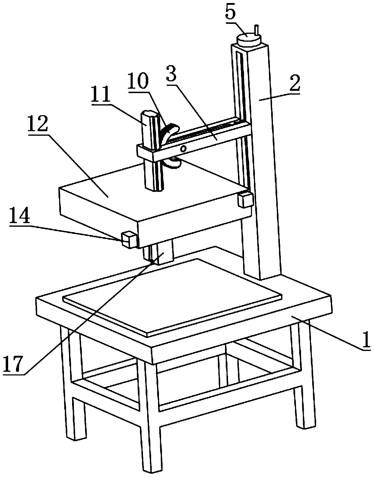
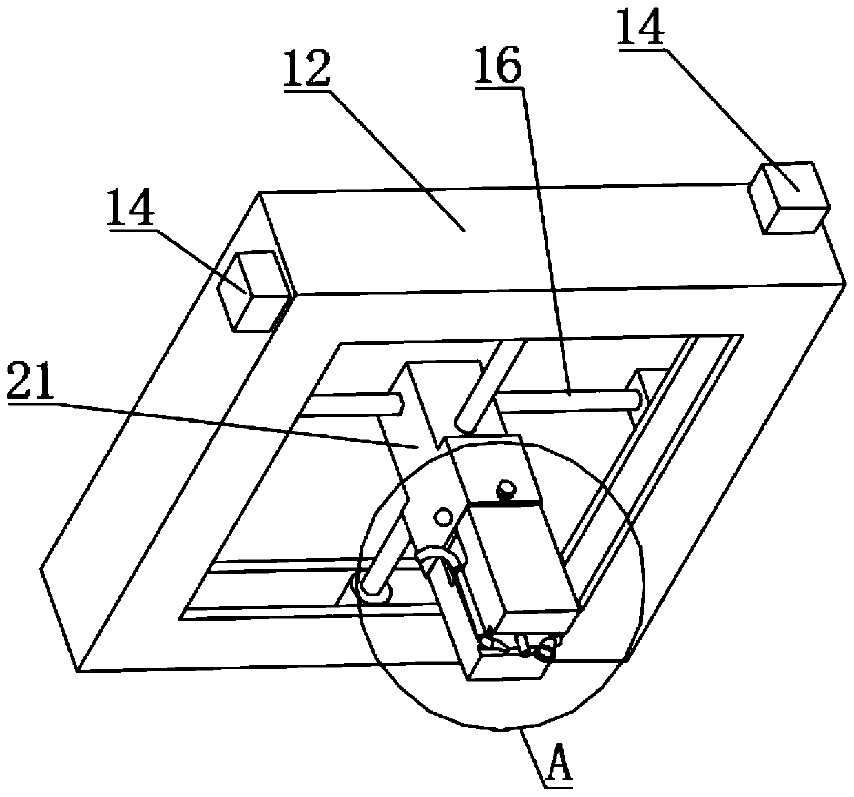
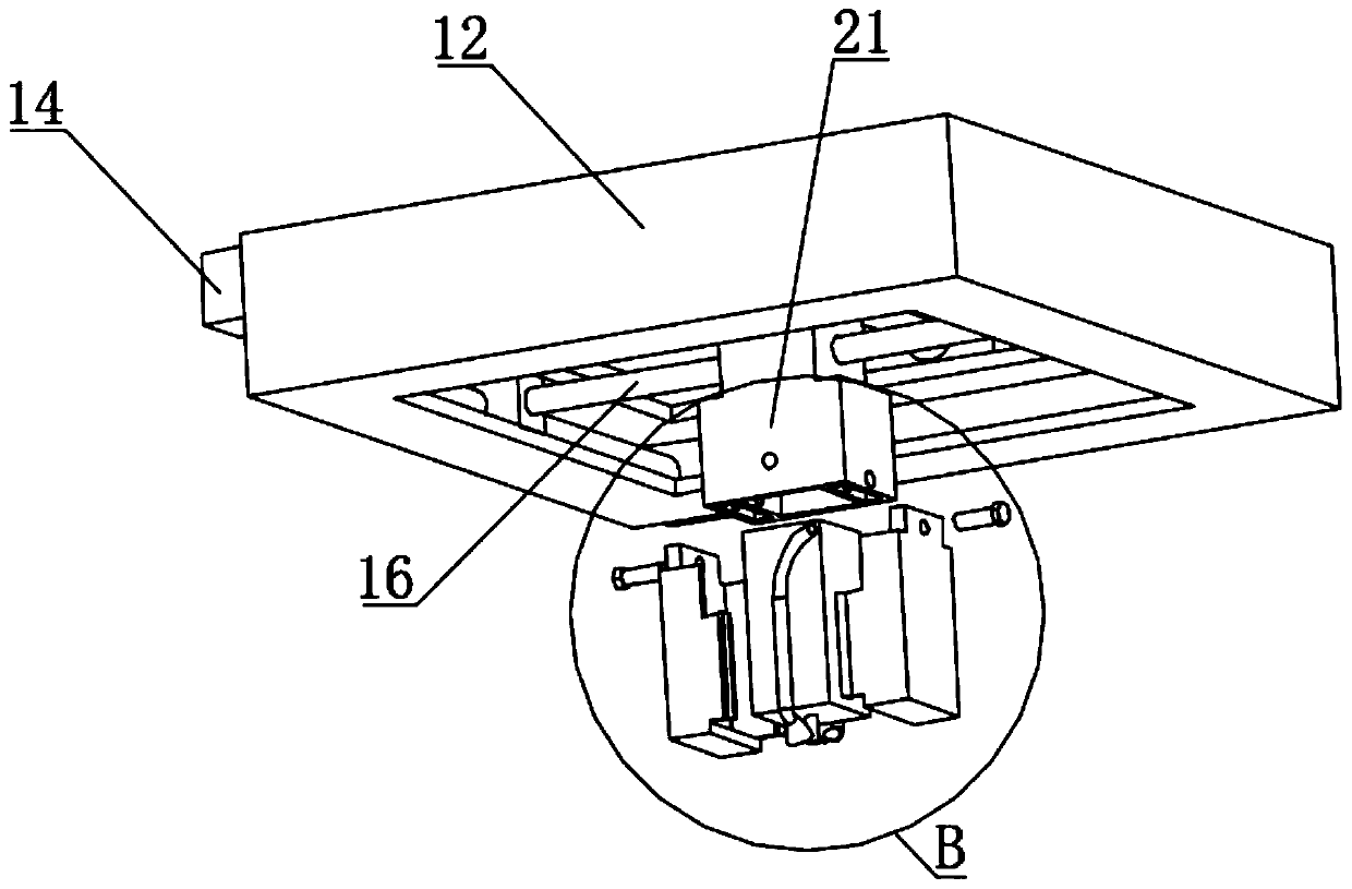
[0023] see Figure 1-7 , the frame structure of the present application includes a bracket 1, a leg is installed under the bracket 1, and the surface of the bracket 1 is fixedly connected with a vertical rod 2, and the vertical rod 2 is connected with a mounting plate 12 through a height adjustment mechanism. The mounting plate 12 is equipped with a sliding block 21 through a driving mechanism, and the sliding block 21 can move up and down through the driving ...


PUM


Abstract

The invention discloses a control frame for laser marking and carving equipment. A support is included. Landing legs are arranged below the support. A vertical rod is fixedly connected to the surfaceof the support and connected with an installing disc through a height adjusting mechanism. The installing disc is provided with a sliding block through a drive mechanism. The sliding block is movablyprovided with two clamping plates. A laser module is clamped and connected in the two clamping plates. The two side walls of the clamping plates are provided with an air blowing pipe and an air suction pipe correspondingly. Lasers emitted by the laser module are used for carving and marking materials, the laser module is connected in the form of the clamping plates, replacement can be convenient and fast, the control frame can adapt to multiple types of laser modules, two pipelines are arranged on the two sides of the laser module, air blowing cleaning and tail gas collecting are conducted onthe material surface, hot melted or gasified substances can be prevented from being gathered on the surface of the carved position, and accordingly the laser acting effect is improved.

Description

technical field [0001] The invention relates to the technical field of laser equipment, in particular to a control frame for laser marking and engraving equipment. Background technique [0002] With the gradual maturity and application development of laser technology, the technology of engraving and marking metal, plastic, wood and other materials with laser has been widely used in industry. Laser marking is to use its high energy density laser to locally irradiate the workpiece, and the focused laser acts on the printing material to melt or even vaporize the surface of the object. By controlling the path of the laser on the surface of the material, the required graphics and text are formed. mark. [0003] First of all, in order to improve the efficiency and effect of laser engraving and marking, the distance between the object and the laser module needs to be set according to the focal length of the module. During the process, it is necessary to adjust the distance betwee...

Claims


Application Information

Patent Timeline
Patent Type & Authority Applications(China)
IPC IPC(8): B23K26/362B23K26/70
CPCB23K26/362B23K26/70B23K26/702
Inventor 张立雄
Owner 徐州立雄智能科技有限公司
Why Eureka
Try Eureka