
Rotating load simulation device

A technology of load simulation and rotating shaft, which is applied in the direction of measuring devices, motor generator testing, instruments, etc., can solve the problems of complex control systems, testing, poor inertia simulation accuracy, etc., achieve high simulation accuracy, wide application range, and reduce requirements Effect

Active Publication Date: 2014-11-19
SHANGHAI SPACEFLIGHT ELECTRONICS & COMM EQUIP RES INST
View PDF10 Cites 14 Cited by
  • Summary
  • Abstract
  • Description
  • Claims
  • Application Information

AI Technical Summary

Problems solved by technology

[0002] The loads of motors and servo mechanisms in actual applications are complex and changeable, and considering that the actual production process cannot be tested under real loads, a system that can simulate mechanical loads in actual applications is provided is required
[0003] At present, the simulation of mechanical load mainly includes three methods: inertia disk, electric simulation, and electro-hydraulic simulation: the manufacturing cost of inertia disk is high, the accuracy of inertia simulation is poor, and it cannot be adjusted to meet the test requirements of different motors or servo mechanisms; electric simulation is to use The conversion characteristics of electrical energy to mechanical energy of the motor, load the test motor or servo mechanism by means of electronically controlled torque, based on the electric model, obtain the loading torque according to the speed change and the actual load mechanical characteristics, and quickly compensate the load motor caused by the speed change The counter electromotive force not only needs real-time calculation, but also requires a complex control system, and its accuracy depends on the precision of the control; the electro-hydraulic simulation consists of two parts: driving and loading, and the electronic control element is a hydraulic cylinder, which has a wider range than the electric simulation. Working frequency and larger output torque, but there are also disadvantages of poor simulation of inertial loads and frictional loads
In addition, electrodynamic simulation and electrohydraulic simulation cannot realize the simulation of dynamic unbalance characteristics of mechanical loads

Method used


Image

  • Rotating load simulation device
  • Rotating load simulation device
  • Rotating load simulation device

Examples


Embodiment Construction

[0023] The technical solutions in the embodiments of the present invention will be clearly and completely described and discussed below in conjunction with the accompanying drawings of the present invention. Obviously, what is described here is only a part of the examples of the present invention, not all examples. Based on the present invention All other embodiments obtained by persons of ordinary skill in the art without creative efforts fall within the protection scope of the present invention.

[0024] In order to facilitate the understanding of the embodiments of the present invention, specific embodiments will be taken as examples for further explanation below in conjunction with the accompanying drawings, and each embodiment does not constitute a limitation to the embodiments of the present invention.

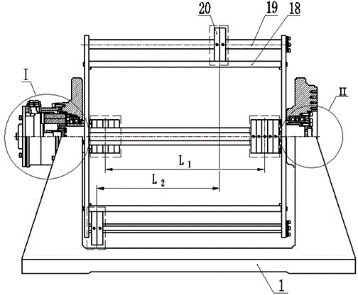
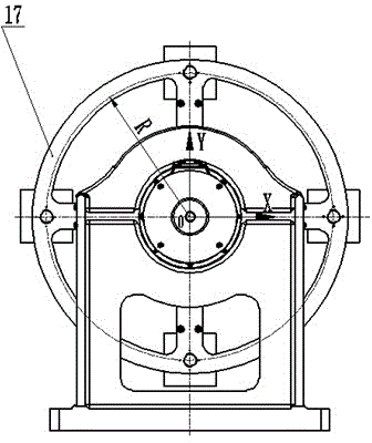
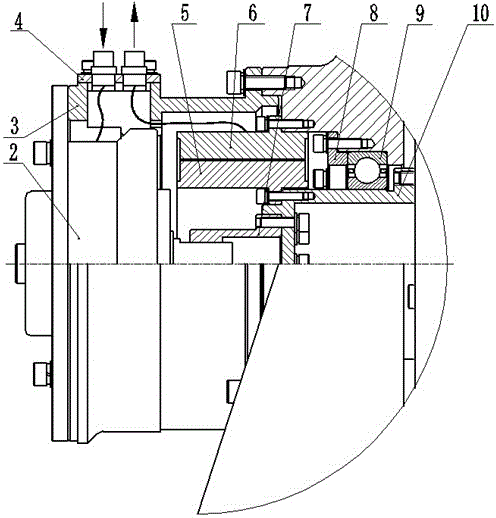
[0025] Such as Figure 1 to Figure 4 As shown, a rotating load simulation device provided by the present invention includes: a base 1, a magnetic powder brake 2, a mount...


PUM


Abstract

The invention discloses a rotating load simulation device. Four guide rods are evenly distributed on the circumference of a rotating shaft R, heavy blocks with the equal mass are installed on every two guide rods symmetric about the rotating shaft, the rotating inertia relative to the rotating shaft is simulated through the mass sum of the heavy blocks on the four guide rods, and the product of inertia under the dynamic unbalance condition is acquired by adjusting the distances between the combination mass centers of the heavy blocks on the symmetric guide rods; the friction moment of a shafting is simulated by controlling excitation currents of a magnetic powder brake. No complex control system is adopted in the rotating load simulation device, the structure is simple, inertia characteristics and friction moment are adjusted conveniently, simulation accuracy is high, and universality is good.

Description

technical field [0001] The invention relates to the technical field of motor and servo mechanism testing, in particular to a rotating load simulation device with adjustable load characteristics. Background technique [0002] The loads of motors and servo mechanisms in actual applications are complex and changeable, and considering that the actual production process cannot be tested under real loads, a system that can simulate mechanical loads in actual applications is provided is required. [0003] At present, the simulation of mechanical load mainly includes three methods: inertia disk, electric simulation, and electro-hydraulic simulation: the manufacturing cost of inertia disk is high, the accuracy of inertia simulation is poor, and it cannot be adjusted to meet the test requirements of different motors or servo mechanisms; electric simulation is to use The conversion characteristics of electrical energy to mechanical energy of the motor, load the test motor or servo mec...

Claims


Application Information

Patent Timeline
IPC IPC(8): G01R31/34G01M13/00
Inventor 周辉史耀强刘明利
Owner SHANGHAI SPACEFLIGHT ELECTRONICS & COMM EQUIP RES INST
Learn More