Supercharge Your Innovation With Domain-Expert AI Agents!

Composite wiring insulation bottle

A technology of insulating bottles and wires, applied in the direction of insulators, supporting insulators, electrical components, etc., can solve the problems of threatening the safety of circuit operators, personal safety, low work efficiency, inconvenient transportation and use, etc., to improve the impact resistance and anti-corrosion Deformability, reduced weight and production costs, and improved repair and replacement capabilities

Inactive Publication Date: 2014-11-19
STATE GRID CORP OF CHINA +1
View PDF6 Cites 1 Cited by
  • Summary
  • Abstract
  • Description
  • Claims
  • Application Information

AI Technical Summary

Problems solved by technology

[0002] At present, in the erection of power transmission lines, the cables and supports are mainly fixed by porcelain bottles. Most of the currently used porcelain bottles are composed of hard insulating materials such as ceramics, glass or glass fiber reinforced plastics. The connecting column is formed at one time, and its weight is relatively large. , and the impact resistance is poor, and it is easy to be damaged by collision, so it is not convenient for transportation and use, and when the insulator or connecting column is damaged, it cannot be disassembled and repaired, and it must be replaced as a whole, which also caused a relatively large A large waste of resources. At the same time, most of the current cables and porcelain bottles rely on wire binding to reliably connect the cable to the porcelain bottle. Because the diameter of the wire binding is relatively small, it takes a lot of time to connect the cable to the porcelain bottle through the wire binding. Work efficiency Underneath, most of the binding wires at the same time are enameled wires, which are conductors, which can easily cause a short circuit in the cable, which seriously threatens the safety of the circuit and the personal safety of the operator.

Method used


Image

  • Composite wiring insulation bottle

Examples


Embodiment Construction

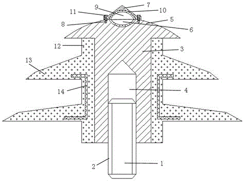
[0011] Such as figure 1 The shown composite wire insulating bottle is composed of a column 1 and an insulator, the outer side of the column 1 is provided with a connecting thread 2, and the insulator is composed of a hard insulating column 3 and an elastic insulating protective sleeve. The elastic insulating protective cover is covered on the outer surface of the hard insulating column 3, and the bottom of the hard insulating column 3 is provided with a connecting screw hole 4 along the axial direction, and the length of the connecting screw hole 4 is not greater than 1 of the length of the hard insulating column 3 / 2, the top of which is provided with a hemispherical pay-off platform 5, and the upper surface of the pay-off platform 5 is additionally provided with a wiring groove 6, a wire crimping cover 7 and connecting bolt holes 8 symmetrically distributed with the wiring groove, wherein the crimping cover 7 is under The surface is provided with a "U"-shaped wire groove 9, ...


PUM


Abstract

The invention discloses a composite wiring insulation bottle which is composed of a column and an insulator. The whole outside body of the column is provided with connection threads. The insulator is composed of a rigid insulation column and an elastic insulation protection sleeve. The elastic insulation protection sleeve coats the outer side of the rigid insulation column. A connection screw hole is arranged at the bottom of the rigid insulation column along the axis direction. A hemispherical pay-off station is arranged at the top. The elastic insulation protection sleeve is composed of a pillar and an umbrella skirt outside the pillar. The pillar and the umbrella skirt are in an integral structure. The rigid insulation column is connected with the pillar through the connection screw hole. According to the invention, the weight and the production cost of a wiring insulation bottle insulator are effectively reduced; production, transportation and carrying are convenient; the anti-impact ability of a wiring insulation bottle is improved; repair and replacement abilities of the wiring insulation bottle are improved; the defect that a cable is fixed on the wiring insulation bottle through a binding wire is overcome; and the stability and the safety of the operation of a power transmission line are further improved.

Description

technical field [0001] The invention relates to a composite wire insulating bottle, which belongs to the field of power transmission and transformation equipment. Background technique [0002] At present, in the erection of power transmission lines, the cables and supports are mainly fixed by porcelain bottles. Most of the currently used porcelain bottles are composed of hard insulating materials such as ceramics, glass or glass fiber reinforced plastics. The connecting column is formed at one time, and its weight is relatively large. , and the impact resistance is poor, and it is easy to be damaged by collision, so it is not convenient for transportation and use, and when the insulator or connecting column is damaged, it cannot be disassembled and repaired, and it must be replaced as a whole, which also caused a relatively large A large waste of resources. At the same time, most of the current cables and porcelain bottles rely on wire binding to reliably connect the cable t...

Claims


Application Information

Patent Timeline
IPC IPC(8): H01B17/14H01B17/16H01B17/40
Inventor 李文华高静
Owner STATE GRID CORP OF CHINA
Features
  • R&D
  • Intellectual Property
  • Life Sciences
  • Materials
  • Tech Scout
  • Unparalleled Data Quality
  • Higher Quality Content
  • 60% Fewer Hallucinations
Learn More