Permanent magnet installation structure of outer rotor motor

An external rotor motor and installation structure technology, applied in the magnetic circuit shape/style/structure, magnetic circuit rotating parts and other directions, can solve the problems of large installation workload of permanent magnets, poor machinability of permanent magnets, and difficulty in ensuring quality, etc. Achieve the effect of improving electromagnetic performance, reducing processing difficulty, and facilitating installation operations

Active Publication Date: 2017-06-27
JIANGXI GONGBU MACHINERY
View PDF4 Cites 1 Cited by
  • Summary
  • Abstract
  • Description
  • Claims
  • Application Information

AI Technical Summary

Problems solved by technology

[0002] The outer rotor of an outer rotor motor usually consists of a cylindrical rotor housing and a permanent magnet located inside the rotor housing. The permanent magnet is fixed on the inner wall of the rotor housing by bonding or screw fastening. This forms the excitation magnetic field of the rotor. When the motor is required to have low-speed and high-torque output, it is often necessary to increase the number of permanent magnets to optimize the distribution of permanent magnets, eliminate or reduce pulsating torque, and reduce copper loss and iron loss. Here Under normal circumstances, the installation and fixation of the permanent magnet is only carried out by bonding, the bonding firmness is poor, the reliability is low, and it is not conducive to quality assurance, and by screwing the permanent magnet, not only the installation workload of the permanent magnet is large, but also due to Poor machinability of permanent magnets also greatly increases production costs, reduces reliability, and makes it difficult to guarantee quality

Method used


Image

  • Permanent magnet installation structure of outer rotor motor
  • Permanent magnet installation structure of outer rotor motor
  • Permanent magnet installation structure of outer rotor motor

Examples


Embodiment Construction

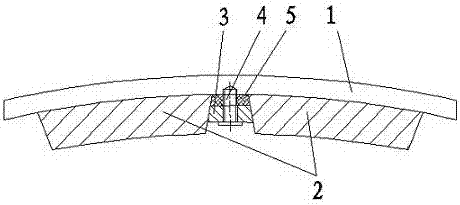
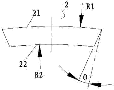
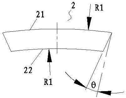
[0008] see figure 1 and 2, the permanent magnet installation structure of the outer rotor motor provided by the present invention includes a cylindrical rotor housing 1 and a number of permanent magnets 2 installed on the inner wall of the rotor housing, and the number of permanent magnets adopts the same tile-shaped hexahedron structure and are regularly arranged in the rotor housing along the circumferential direction (direction along the circumference) and the axial direction (direction parallel to the axis of the stator main shaft), and the two circumferential sides of the permanent magnets are chamfered inside In the shape of an inclined plane, axially extending longitudinal pressure strips 3 are arranged between adjacent permanent magnets in the circumferential direction, and the longitudinal pressure strips are fastened to the rotor housing by screws 4. The circumferential direction of the longitudinal pressure strips The two sides are respectively pressed against the c...


PUM


Abstract

The invention relates to a permanent magnet installation structure of an outer rotor motor, comprising a cylindrical rotor shell and several permanent magnets installed on the inner wall of the rotor shell, the several permanent magnets adopt the same tile-shaped hexahedron structure and The inside of the rotor housing is regularly arranged along the circumferential direction and the axial direction. The two circumferential sides and the two axial sides of the permanent magnets are all in the shape of an inclined plane with chamfered inner sides. The circumferential direction and the axial direction An axially extending longitudinal bar and a circumferentially extending transverse bar are respectively arranged between upward adjacent permanent magnets, and the longitudinal bar and the transverse bar are fastened to the rotor housing by screws and The permanent magnet is compressed and fixed. The permanent magnet of the present invention has simple installation process, good firmness and reliability, and low processing cost, which is beneficial to optimize the rotor magnetic field, reduce vibration, reduce noise, reduce heat loss and control temperature rise, and is especially suitable for low-speed and high-torque external rotor motors And according to the reel direct drive crane hoisting mechanism of this motor, etc.

Description

technical field [0001] The invention relates to a permanent magnet installation structure of an outer rotor motor, in particular to a low-speed, high-torque outer rotor permanent magnet synchronous motor. Background technique [0002] The outer rotor of an outer rotor motor usually consists of a cylindrical rotor housing and a permanent magnet located inside the rotor housing. The permanent magnet is fixed on the inner wall of the rotor housing by bonding or screw fastening. This forms the excitation magnetic field of the rotor. When the motor is required to have low-speed and high-torque output, it is often necessary to increase the number of permanent magnets to optimize the distribution of permanent magnets, eliminate or reduce pulsating torque, and reduce copper loss and iron loss. Here Under normal circumstances, the installation and fixation of the permanent magnet is only carried out by bonding, the bonding firmness is poor, the reliability is low, and it is not condu...

Claims


Application Information

Patent Timeline
Patent Type & Authority Patents(China)
IPC IPC(8): H02K1/27H02K1/28
Inventor 彭祖军郭希文喻林
Owner JIANGXI GONGBU MACHINERY
Why Eureka
Try Eureka