
Self-plugging audio test jig, and self-plugging audio test method

An audio test and fixture technology, applied in electrical components and other directions, can solve the problems of heavy workload, equipment complexity, high operation and maintenance costs, low test efficiency, etc., to achieve the effect of improving convenience and efficiency and reducing costs

Inactive Publication Date: 2014-11-19
南京声准科技有限公司
View PDF5 Cites 8 Cited by
  • Summary
  • Abstract
  • Description
  • Claims
  • Application Information

AI Technical Summary

Problems solved by technology

Operations such as loading and plugging need to be done manually, which has the disadvantages of heavy workload and low testing efficiency, which has become the bottleneck of industrial assembly line production
[0003] At present, there is an automatic equipment that sends the tested mobile phone and other terminals into the muffler box through the drawer driven by the first cylinder, and installs the audio plug driven by the second cylinder in the muffler box for plugging and unplugging operations, and the installed third cylinder Drive plugging and unplugging the USB, the fourth and fifth cylinders are used to press the mobile phone and other terminals from above, so that multiple sets of cylinders and solenoid valves are required to perform actions, and the actions of completing the entry and exit of the mobile phone, automatic plugging and unplugging of the earphone and USB need to be independent of each other Four or five sets of cylinders and solenoid valves, resulting in relatively high equipment complexity and operation and maintenance costs

Method used


Image

  • Self-plugging audio test jig, and self-plugging audio test method
  • Self-plugging audio test jig, and self-plugging audio test method
  • Self-plugging audio test jig, and self-plugging audio test method

Examples


Embodiment 1

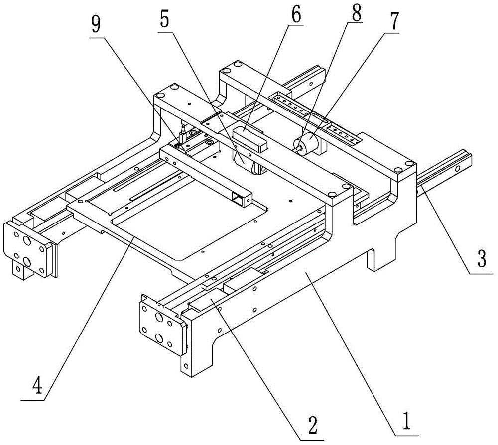
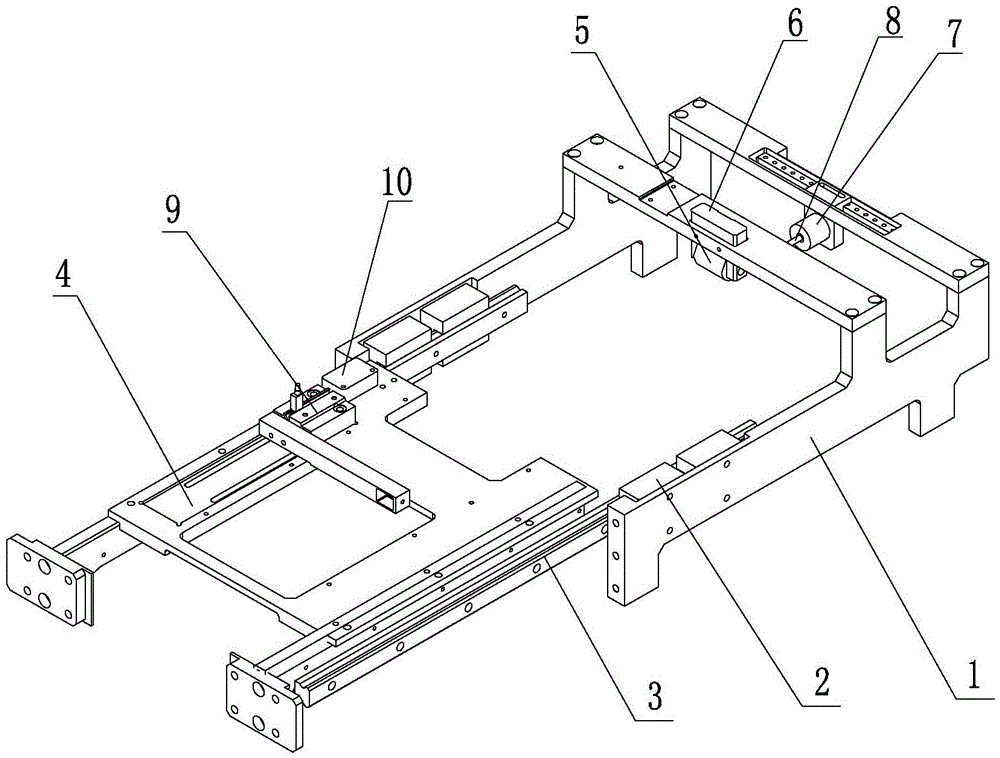
[0029] The self-plugging audio test fixture of the present embodiment is as figure 1 and figure 2 As shown, it is used for the mobile phone audio online test at the factory side, and the corresponding terminal to be tested is a mobile phone with a USB interface and an audio interface at both ends, and can complete the automatic plugging and unplugging operation of each interface in the audio test.

[0030] The whole set of devices is installed in the muffler box, so the whole muffler box is omitted in the figure. The guide rail bracket 1 fixedly installed in the muffler box, the guide rail bracket 1 slides and cooperates with the drawer 4 through the slider 2 and the guide rail 3 .

[0031] Roller 5 and audio plug 7 are installed on the guide rail bracket 1, and wherein roller 5 is fixed on mobile phone top by roller bracket 6, presses down mobile phone when drawer 4 enters muffler box, does not allow it to be upturned when inserting, has guaranteed smooth insertion.

[003...

Embodiment 2

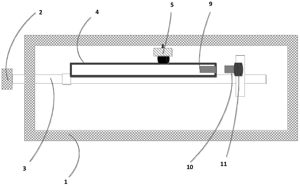
[0044] The self-plugging audio test fixture of this embodiment is used to test the terminal under test whose audio jack and USB are on the same side. Its structure diagram is as follows image 3 and Figure 4 As shown, it includes a mute box 1, a suitable container 2 (such as a drawer) for carrying the terminal to be tested, an entry and exit slide rail 3 of the container 2, a terminal to be tested 4, an adjustable roller 5 installed at a suitable position, and a terminal to be tested 4. earphone port 6 installed in a suitable position, a USB port on the terminal 4 to be tested, and a USB plug 10 installed in a suitable position; the earphone plug 7 is installed on the test box 1 through a flexible device 8; the USB The plug 10 is mounted on the test box 1 by some flexible means 11 .

[0045] The terminal 4 to be tested is placed in the container 2, and the roller 5 presses the terminal 4 to be tested when the terminal 4 to be tested enters the test box 1, and then the earphon...


PUM


Abstract

The present invention discloses a self-plugging audio test jig, and a self-plugging audio test method. The jig comprises an audio plug fixed in a whistle box and a container going in and out the whistle box. When the container goes in or out the whistle box, the audio plug can be plugged in or out. The method comprises the steps of placing a to-be-tested terminal in the container, enabling the container to enter the whistle box to plug an audio interface automatically, carrying out the audio test, plugging out the audio interface automatically when the container quits, etc. According to the present invention, the thrust generated by that the container goes in or out the whistle box drives the to-be-tested terminal to plug in or out the plug, so that the test automation and usability are guaranteed, the cost is reduced, and the test efficiency is improved.

Description

technical field [0001] The invention relates to an automatic testing device based on audio performance and quality, and a testing method for the device, in particular to a self-plugging audio testing fixture and method. Background technique [0002] Due to the performance difference of audio devices and the impact of other factors in the manufacturing process on the audio of terminals such as mobile phones, online audio testing is required during mobile phone production. At present, the testing system and method of the audio frequency disclosed in CN101426167A are mainly used: the mobile phone is loaded in the test fixture and inserted into the audio connector; The connector inputs the test signal and outputs the test result. After the test is completed, the fixture is taken out from the silencer box, and the audio connector is manually unplugged. Operations such as loading and plugging need to be completed manually, which has the disadvantages of heavy workload and low tes...

Claims


Application Information

Patent Timeline
Patent Type & Authority Applications(China)
IPC IPC(8): H04R29/00
Inventor 张铭闫杰
Owner 南京声准科技有限公司
Learn More