A LED smart light bulb drive power supply

A technology for driving power supply and smart light bulbs, which is applied in the direction of electric light source, electric light circuit layout, light source, etc. It can solve the problems of increasing the cost and selling price of smart light bulbs, affecting the beautiful user experience of products, and hindering the popularization of smart light bulbs in the market, so as to achieve simplicity and reliability. Dimming control, meet the standby power consumption requirements, overcome the tedious effect of control

Active Publication Date: 2017-02-01
FOSHAN TOPDAY OPTOELECTRONICS TECH
View PDF10 Cites 0 Cited by
  • Summary
  • Abstract
  • Description
  • Claims
  • Application Information

AI Technical Summary

Problems solved by technology

In the traditional multi-output dimming circuit, each channel needs a separate and complete DC-DC conversion module, and each module needs a main control IC, a power inductor, an output electrolytic capacitor and several control circuits, which greatly increases the The cost and selling price of smart light bulbs have seriously hindered the market popularization of smart light bulbs; it will make the circuit too bloated, and the standby power consumption will rise sharply; and it will increase the difficulty of PCB design, and the volume of the light bulb will have to be made very large. Affects product aesthetics and user experience

Method used


Image

  • A LED smart light bulb drive power supply
  • A LED smart light bulb drive power supply
  • A LED smart light bulb drive power supply

Examples


Embodiment Construction

[0029]The specific embodiment of the present invention will be further described below in conjunction with accompanying drawing:

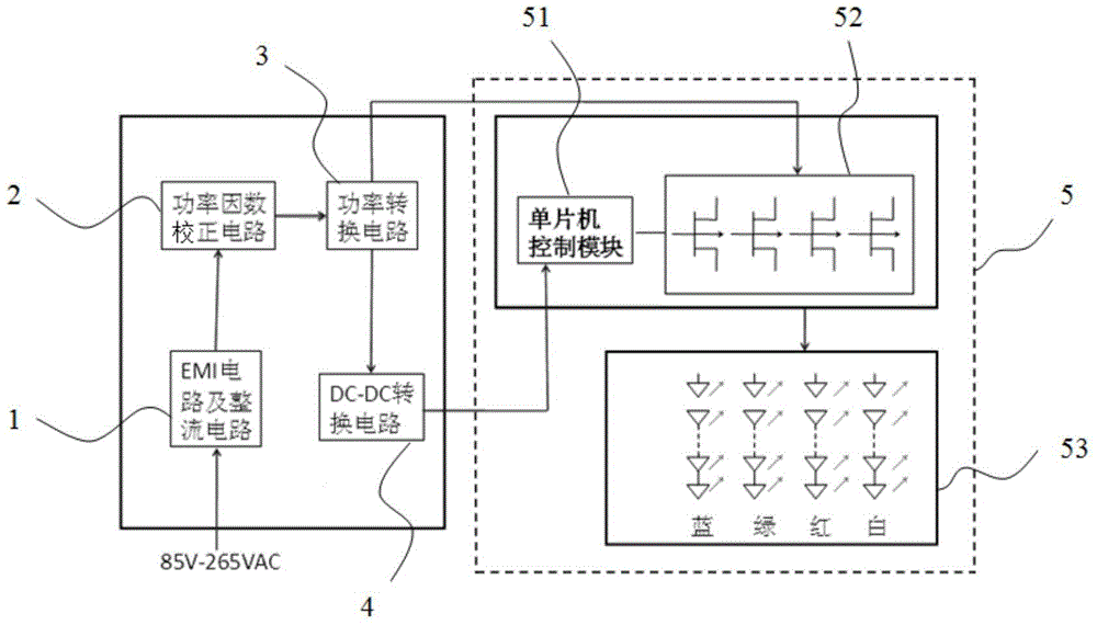
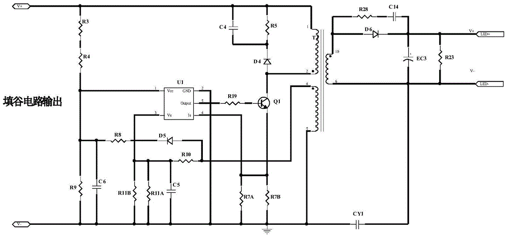
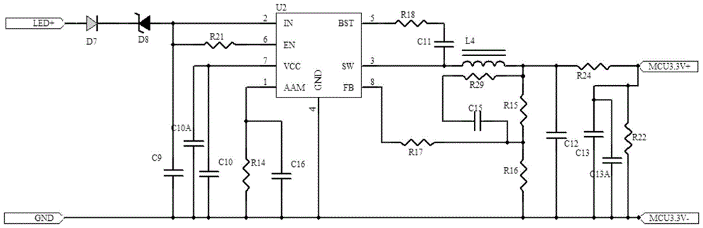
[0030] Refer to attached figure 1 To attach image 3 As shown, a driving power supply for an LED smart light bulb includes an EMI filter circuit and a rectifier circuit module 1 , a power factor correction circuit 2 , a power conversion circuit 3 , a DC-DC conversion circuit 4 and a dimming control circuit 5 . The input end of the driving power supply is connected to the EMI filter circuit, the output end of the EMI filter circuit is connected to the input end of the rectification circuit, and the output end of the rectification circuit is connected to the input end of the power factor correction circuit 2, The output end of the power factor correction circuit 2 is connected to the input end of the power conversion circuit 3, and the output end of the power conversion circuit 3 is connected to the MOS tube group. The dimming control circuit 5 inc...


PUM


Abstract

The invention discloses a driving power source for a smart LED bulb. The driving power source comprises an EMI filtering circuit, a rectifying circuit, a power factor correcting circuit, a power converting circuit, a DC-DC converting circuit and a dimming control circuit, wherein the power factor correcting circuit comprises a valley filling circuit and an electrolytic capacitor connected to the valley filling circuit, and the output end of the valley filling circuit is connected with the input end of the power converting circuit; the power converting circuit is a primary side feedback power converting circuit, and the output end of the power converting circuit is connected with the dimming control circuit; the dimming control circuit comprises a single-chip microcomputer control module and an MOS transistor, the input end of the DC-DC converting circuit is connected with the output end of the power converting circuit, the output end of the DC-DC converting circuit is connected with the single-chip microcomputer control module, and the switch-on duty ratio of the MOS transistor is controlled through the single-chip microcomputer control module so that dimming and color modulation on loads can be achieved. The driving power source for the smart LED bulb is low in cost, small in size and low in power consumption; the driving power source meets the requirement for a high power factor and the requirement for non-flickering lighting of the bulb at the same time.

Description

technical field [0001] The invention belongs to the technical field of LED driving power supply, and in particular relates to a driving power supply for LED smart light bulbs. Background technique [0002] With the breakthrough of LED new optical design, the development of new lamps and the improvement of control software make the use of LED lighting more convenient. The emergence of LED smart bulbs further reflects the broad prospects of LED light-emitting diodes in lighting applications. With the development of intelligent control technology and Internet technology, the smart home market is becoming more and more mature. LED smart light bulbs adopt the core technology of embedded Internet of Things, embed the intercommunication core module into energy-saving light bulbs, and introduce the software mechanism of interactive services into the living room, relying on the cloud service platform The support constitutes a smart light bulb system that can be linked, socialized, a...

Claims


Application Information

Patent Timeline
Patent Type & Authority Patents(China)
IPC IPC(8): H05B37/02
Inventor 方彬辉
Owner FOSHAN TOPDAY OPTOELECTRONICS TECH
Why Eureka
Try Eureka