Electric linear actuator

A linear actuator, electric technology, applied in the direction of electric components, electrical components, electromechanical devices, etc., can solve the problems of increasing the size and power consumption of electric motors, increasing power loss, etc.

Active Publication Date: 2014-11-19
NTN CORP
View PDF5 Cites 19 Cited by
  • Summary
  • Abstract
  • Description
  • Claims
  • Application Information

AI Technical Summary

Problems solved by technology

These motion conversion mechanisms involve sliding contacts, thereby increasing power los

Method used


Image

  • Electric linear actuator
  • Electric linear actuator
  • Electric linear actuator

Examples


Embodiment approach

[0036] Hereinafter, a preferred embodiment of the present invention will be described with reference to the accompanying drawings.

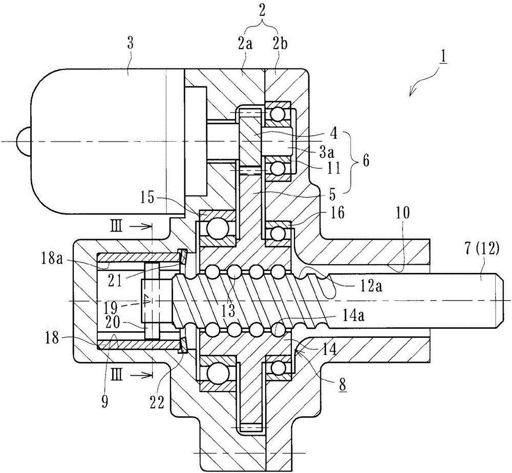
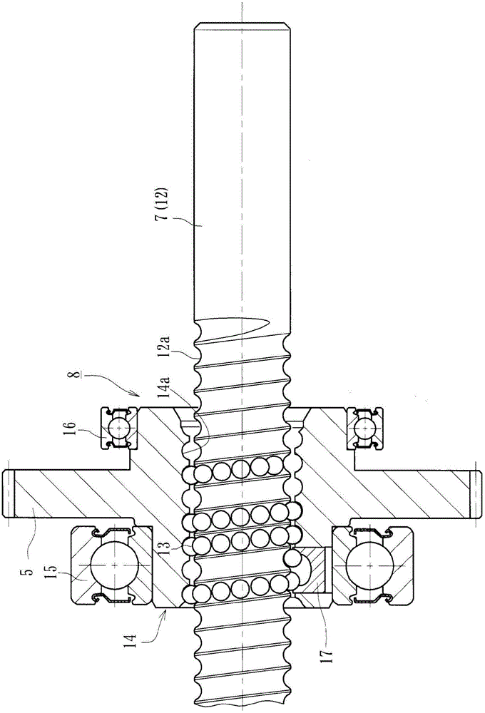
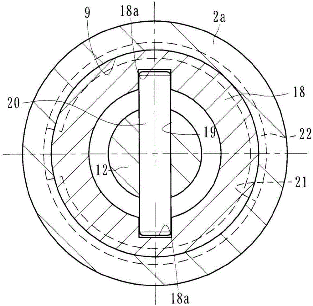
[0037] figure 1 is a longitudinal sectional view showing a preferred embodiment of the electric linear actuator of the present invention; figure 2 is showing figure 1 Longitudinal cross-sectional view of the ball screw mechanism of the electric linear actuator; image 3 is along figure 1 The sectional view taken along the line III-III; Figure 4 is a partial enlarged view showing the mounting portion of the stop ring; Figure 5 (a) is a side view of the snap ring of the present invention, and Figure 5 (b) is Figure 5 a front view of (a); and Image 6 It is an explanatory drawing showing the attachment part of the conventional snap ring.

[0038] Such as figure 1 As shown, the electric linear actuator 1 of the present invention includes: a cylindrical housing 2, an electric motor 3 mounted on the housing 2, a reduction mechanism 6,...


PUM


Abstract

[Aim] Provided is an electric linear actuator that is capable of reducing sliding friction and wear and that has a simple structure for cost reduction. [Solution] In an electric linear actuator that includes a ball screw mechanism (8) which converts a rotational motion of an electric motor (3) into a linear motion in an axial direction of a driving shaft (7) via a speed reduction mechanism (6), a cylindrical sleeve (18) is fitted into a housing hole (9) of a housing (2a), and a pair of recessed grooves (18a) are formed at opposing positions extending in an axial direction in an inner periphery of the sleeve (18) so that a guide pin (20) implanted in a tip portion of a screw axis (12) is engaged. An annular groove (21) is formed in an opening portion of the housing hole (9) of the housing (2a), and the sleeve (18) is retained in a pressed state by a hole retaining ring (22) that is mounted on the annular groove (21) and provided with a curved portion which has peaks at positions that are symmetrical to a cut-out portion.

Description

technical field [0001] The present invention relates to an electric linear actuator provided with a ball screw mechanism used in driving parts of electric motors and automobiles, etc. , An electric linear actuator for converting rotational motion from an electric motor into linear motion of a drive shaft via a ball screw mechanism. Background technique [0002] In electric linear actuators used in various drive sections, as a mechanism for converting the rotational motion of the electric motor into axial linear motion, gears such as trapezoidal screw worm gear mechanisms or rack-and-pinion gear mechanisms are generally used mechanism. These motion conversion mechanisms involve sliding contacts, thereby increasing power loss, thus necessitating an increase in the size and power consumption of the electric motor. Therefore, ball screw mechanisms have been widely used as more efficient actuators. [0003] In the prior art electric linear actuator, an output member connected ...

Claims


Application Information

Patent Timeline
IPC IPC(8): F16H25/24F16B21/18F16H25/20F16H25/22H02K7/06
CPCH02K7/06F16B21/183F16H25/2214F16H2025/2081F16H25/24Y10T74/18576F16H25/2204
Inventor 池田良则船田健介
Owner NTN CORP
Why Eureka
Try Eureka