
Side sealing device of thermal treatment furnace

A heat treatment furnace and side sealing technology, which is applied to the sealing of engines, engine components, mechanical equipment, etc., can solve the problems of sand affecting the working environment, high labor intensity, and high cost, and achieve convenient and quick operation, good sealing effect, and long service life long effect

Active Publication Date: 2014-11-26
张家港市伟业机械制造有限公司
View PDF10 Cites 2 Cited by
  • Summary
  • Abstract
  • Description
  • Claims
  • Application Information

AI Technical Summary

Problems solved by technology

[0002] The side sealing device of the heat treatment furnace is the side edge sealing device between the heat treatment furnace (also known as the heating furnace) and the furnace car, such as the Chinese patent No. 2009202417540 applied by the applicant on December 11, 2009, the patent In the name "Multi-station Heat Treatment Furnace", there is a gap between the furnace car transported to the bottom of both sides of the furnace body, which needs to be sealed. However, the existing seals generally use sand sealing grooves for sealing, which are filled in the sealing grooves. There is sand for sealing, but with this sealing structure, the sand is easy to fall, affecting the sealing effect, and the operation is inconvenient, and it is often necessary to manually fill the sand, which is cumbersome and labor-intensive, and the sand falling also affects the working environment. The cost of sand transportation for secondary filling is high, and the sealing performance is relatively poor

Method used


Image

  • Side sealing device of thermal treatment furnace
  • Side sealing device of thermal treatment furnace
  • Side sealing device of thermal treatment furnace

Examples


Embodiment Construction

[0020] The preferred embodiments of the present invention will be described in detail below in conjunction with the accompanying drawings, so that the advantages and features of the present invention can be more easily understood by those skilled in the art, so as to define the protection scope of the present invention more clearly.

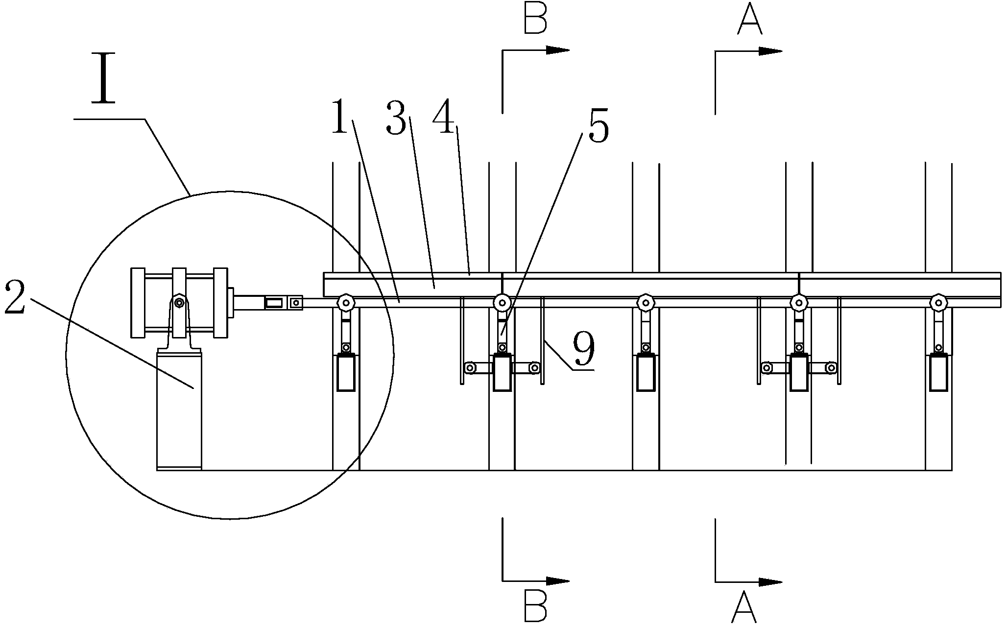
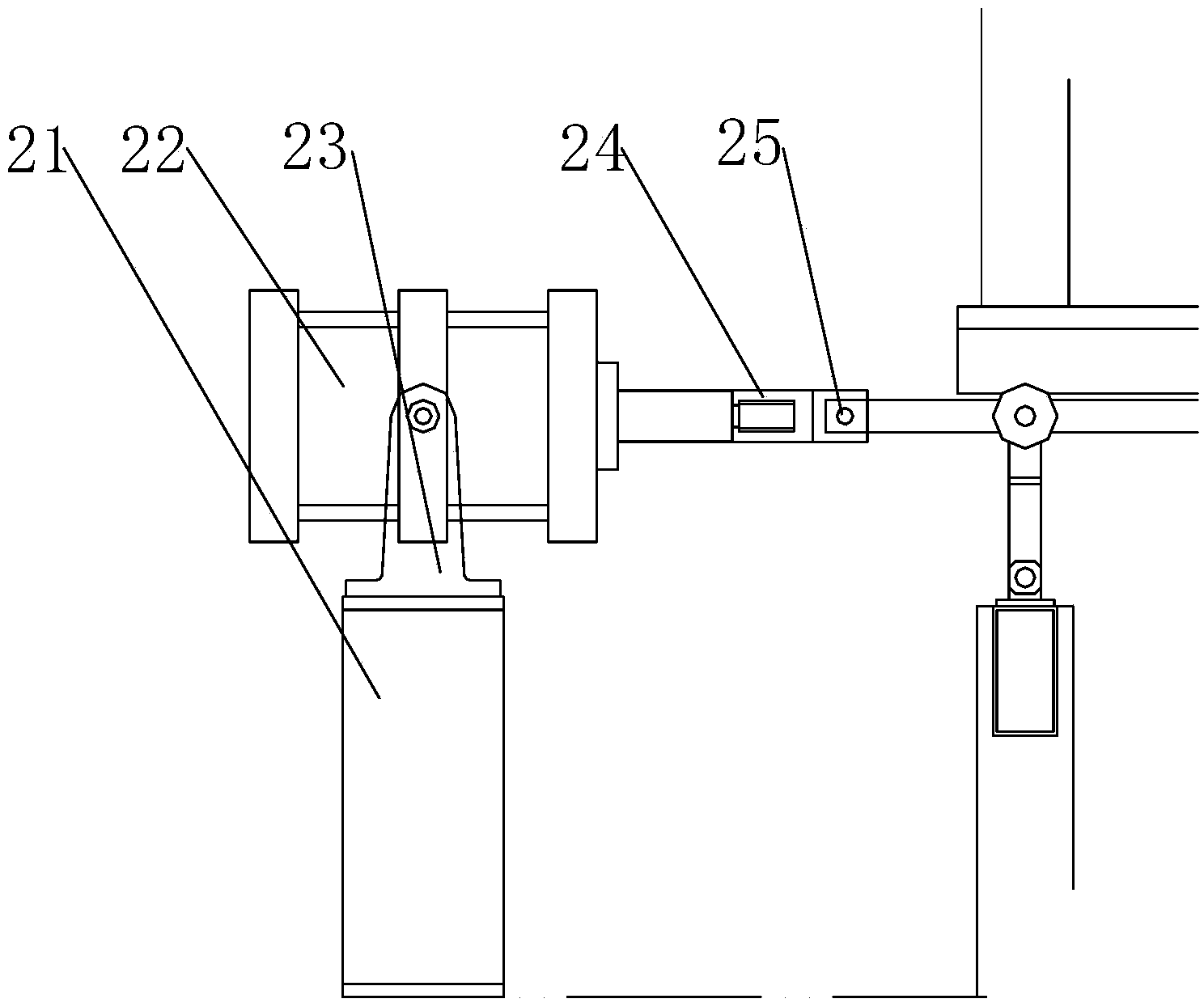
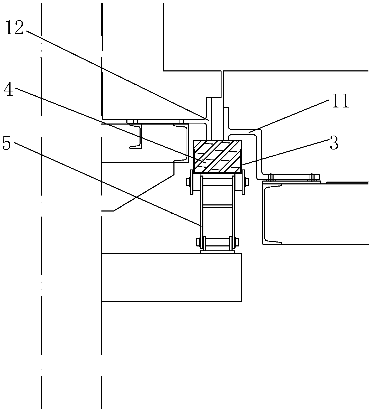
[0021] refer to Figure 1 to Figure 8 As shown, a side sealing device of a heat treatment furnace includes a power unit 2, a tie rod 1 connected to the power unit 2, and a sealing groove 3 arranged above the tie rod 1, and is arranged in the sealing groove 3 for sealing and heating The sealing block 4 for the gap between the furnace and the furnace car, the tugboat assembly 5 movably connected with the pull rod 1, the tugboat support 8 connected with the tugboat assembly 5 and fixed on the furnace body without moving, and the tugboat support 8 two The roller frame 7 connected to the side, the roller 6 connected with the roller frame 7, and the gu...


PUM


Abstract

The invention discloses a side sealing device of a thermal treatment furnace. The side sealing device of the thermal treatment furnace comprises a power device, a pull rod, a sealing groove, a sealing block, a tugging wheel assembly, a tugging wheel support, a rolling wheel carrier, a rolling wheel and guiding tracks. The side sealing device of the thermal treatment furnace drives the pull rod through an air cylinder, the strip-shaped sealing groove is formed in the pull rod, the sealing block for sealing a gap between a heating furnace and a furnace car is installed in the sealing groove to enable the sealing block to seal the gap, operation is convenient and quick, and the sealing effect is good. The guiding tracks are further fixed at the bottom of the sealing groove, and the rolling wheel fixed on the support and the tugging wheel assembly are further arranged in the guiding tracks on two sides, so that the effect that the side sealing device is movably connected with a furnace body is played. In addition, the service life is long, and the pneumatic sealing cost is low.

Description

technical field [0001] The invention relates to a sealing device, in particular to a side sealing device of a heat treatment furnace. Background technique [0002] The side sealing device of the heat treatment furnace is the side edge sealing device between the heat treatment furnace (also known as the heating furnace) and the furnace car, such as the Chinese patent No. 2009202417540 applied by the applicant on December 11, 2009, the patent In the name "Multi-station Heat Treatment Furnace", there is a gap between the furnace car transported to the bottom of both sides of the furnace body, which needs to be sealed. However, the existing seals generally use sand sealing grooves for sealing, which are filled in the sealing grooves. There is sand for sealing, but with this sealing structure, the sand is easy to fall, affecting the sealing effect, and the operation is inconvenient, and it is often necessary to manually fill the sand, which is cumbersome and labor-intensive, and ...

Claims


Application Information

Patent Timeline
IPC IPC(8): F16J15/16C21D1/00
Inventor 肖献忠杜文安陈波
Owner 张家港市伟业机械制造有限公司
Learn More