Automobile embedded knob switch endurance test device

A technology of knob switch and durability test, which is applied in the field of automobiles, can solve the problems of difficulty in meeting the requirements of the size of the knob operating force, low degree of automation, and low work efficiency, so as to improve the degree of intelligence and test accuracy, and improve the degree of intelligence , Improve the effect of test accuracy

Active Publication Date: 2014-11-26
GREAT WALL MOTOR CO LTD
View PDF7 Cites 5 Cited by
  • Summary
  • Abstract
  • Description
  • Claims
  • Application Information

AI Technical Summary

Problems solved by technology

[0003] 1. In the prior art, the built-in knob switch is driven by the flexible wheel, and the flexible wheel is in line contact with the knob, which is prone to relative sliding, so the reliability of the test results cannot be guaranteed;
[0004] 2. Adjust the friction force of the knob by manually adjusting the clamping height of the switch, it is impossible to visually check the friction force, and it is difficult to meet the requirements of the knob for the operation force;
[0005] 3. Indirectly judge whether the switch is rotated in place according to the rotation angle of the stepping motor, and the error in the action of the knob cannot be found and corrected in time, and the accuracy of the test result cannot be guaranteed;
[0006] 4. The adjustment of the equipment needs to be done manually, the degree of automation is not high, and the work efficiency is low

Method used


Image

  • Automobile embedded knob switch endurance test device
  • Automobile embedded knob switch endurance test device
  • Automobile embedded knob switch endurance test device

Examples


Embodiment Construction

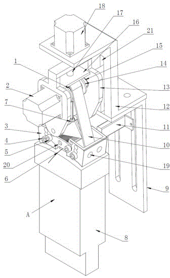
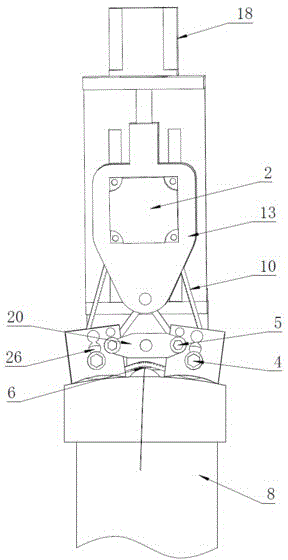
[0030] see Figure 1 to Figure 7 , the present invention mainly includes a driving gear 1, a test motor 2, a driven roller bracket 3, a strain gauge pressure sensor 6, an adaptive triangular bracket 7, a sensor bracket 9, a timing belt 10, a color sensor 11, an equipment bracket 12, an active Gear support 13, limit piece 14, leading screw limit plate 16, leading screw pair 17, pressing motor 18, fixed plate 20, vertical slide rail 21 and driven roller 26. The main components function as follows:

[0031] Compression motor 18: drives the screw pair 17 to rotate;

[0032] Lead screw pair 17: drive the driving gear bracket 13 to rise or fall through rotation;

[0033] Lead screw limiting plate 16: limit the rising height of the driving gear bracket 13, and prevent the lead screw from interfering with the synchronous belt;

[0034] Drive gear bracket 13: fix the drive gear 1 and the test motor 2, and its side has a dovetail slider matching the vertical slide rail 21 to ensure t...


PUM


Abstract

The invention provides an automobile embedded knob switch endurance test device. The automobile embedded knob switch endurance test device comprises a compression motor, a lifting support, a test motor, a synchronous belt, a driving gear and two driven rolling wheels, wherein the test motor, the synchronous belt, the driving gear and the two driven rolling wheels are installed on the lifting support. The compression motor is vertically fixed to an equipment support and located above a tested switch. The compression motor drives the lifting support between the tested switch and the compression motor through a lead screw pair. The two driven rolling wheels are located on the two sides of a knob of the tested switch respectively. The driving gear is located above the tested switch and is in butt joint with an output shaft of the test motor. The synchronous belt is wound around the driving gear and the two driven rolling wheels and pressed against the knob of the tested switch. According to the automobile embedded knob switch endurance test device, the two driven rolling wheels presses the synchronous belt which drives the knob of the tested switch to rotate on the knob, so that surface contact between the synchronous belt and the knob is realized, relative sliding between the synchronous belt and the knob is effectively prevented, and reliability of test results is guaranteed.

Description

technical field [0001] The invention relates to a device for performing durability tests on built-in rotary switches used in automobiles, belonging to the technical field of automobiles. Background technique [0002] Knob switches have been widely used in automobiles. In order to ensure the reliability of the switches, durability tests are required. At present, the more advanced built-in knob switch durability test device is driven by a stepping motor and a flexible wheel in friction contact with the knob of the switch drives the knob to rotate. The rotation angle of the knob is controlled by the stepping motor. The switch knob provides rotational friction, and the size of the friction is adjusted by manually adjusting the relative position of the knob and the flexible wheel. There are following deficiencies in this test device: [0003] 1. In the prior art, the built-in knob switch is driven by the flexible wheel, and the flexible wheel is in line contact with the knob, w...

Claims


Application Information

Patent Timeline
Patent Type & Authority Applications(China)
IPC IPC(8): G01M13/00
Inventor 余天刚闫恒娜赵路涛康兰英李金广刘明伟展亚辉
Owner GREAT WALL MOTOR CO LTD
Why Eureka
Try Eureka