
Flat panel display panel uniformity detection method and system

A flat-panel display and detection method technology, applied in the direction of instruments, testing optical properties, optics, etc., can solve the problems of increased detection cost, uneven imaging brightness, and difficulty in detection, and achieve the effect of saving detection cost and detection time

Inactive Publication Date: 2014-11-26
TOP VICTORY INVESTMENTS
View PDF5 Cites 11 Cited by
  • Summary
  • Abstract
  • Description
  • Claims
  • Application Information

AI Technical Summary

Problems solved by technology

[0003] In view of this, many countries in the world have invested a lot of manpower and funds in the research of display technology, which has led to the rapid improvement of display technology. Defects (such as Mura defects that are often heard) and problems such as uneven brightness of the image will greatly reduce product quality. However, these defects are often difficult to detect by human eyes in the early stage, so it is necessary to rely on a complete set of And the precise detection system can detect the brightness uniformity and color of the liquid crystal display, and can accurately detect the position and size of the defect in the early stage of the product defect, and carry out precise detection and control of the product, thereby improving product quality
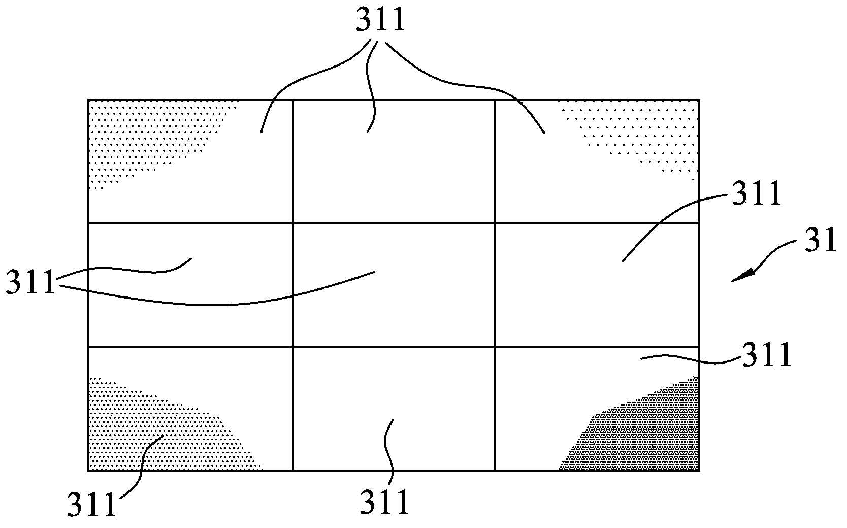
[0004] In the common detection method, the light-emitting surface of the panel to be tested is mainly divided into nine equal parts, and tested one by one by a detection device, such as BM-5A, BM-7A, CS-200O and CA-210 Its luminance value and chromaticity value, when the number of panels to be tested to be tested is large, it is very time-consuming to use this method and it is necessary to purchase related testing instruments, which leads to increased testing costs. Therefore, it is necessary to find a solution

Method used


Image

  • Flat panel display panel uniformity detection method and system
  • Flat panel display panel uniformity detection method and system
  • Flat panel display panel uniformity detection method and system

Examples


Embodiment Construction

[0021] The present invention will be described in detail below with reference to the drawings and embodiments.

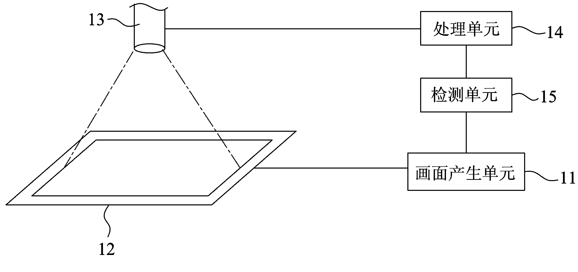
[0022] Refer to figure 1 A preferred embodiment of the flat panel display panel uniformity detection method of the present invention is implemented by a panel uniformity detection system. The panel uniformity detection system includes an image generating unit 11, at least one panel to be tested 12, an image capturing unit 13, a processing unit 14 and a detection unit 15.

[0023] The picture generating unit 11 is electrically connected to the panel 12 to be tested, and can be used to generate a picture to be tested according to a control command to input the picture to be tested to the panel 12 to be tested. The implementation aspect of the image capturing unit 13 is a CMOS image sensor or a CCD image sensor, but not limited to this, the image capturing unit 13 can be used to capture images displayed on the panel 12 under test. The processing unit 14 is electrically con...


PUM


Abstract

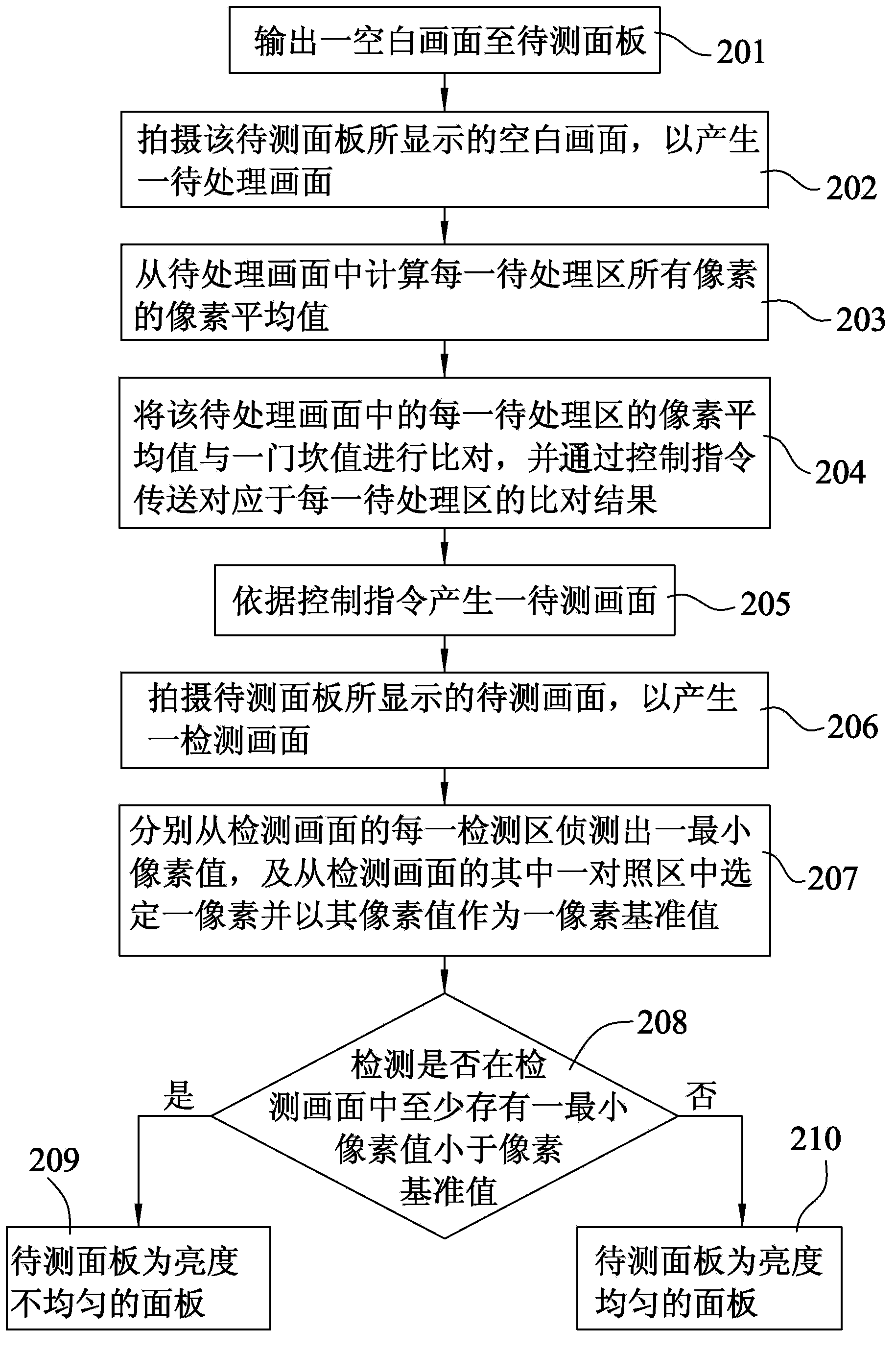
The invention discloses a flat panel display panel uniformity detection method and system. The detection method comprises the following steps that a frame generating unit generates a frame to be detected according to a control instruction, wherein the frame to be detected is used for being displayed on a panel to be detected; a frame obtaining unit shoots the frame which is to be detected and is displayed on the panel to be detected so that a detection frame comprising a plurality of detection areas and a plurality of contrast areas can be generated; a processing unit detects a minimum pixel value from each detection area of the detection frame, selects a pixel from one contrast area in the detection frame and takes the value of the pixel of the contrast area as a pixel reference value; a detection unit detects in the detection frame whether at least one minimum pixel value smaller than the pixel reference value exists or not, and if yes, the detection unit determines that the panel to be detected is a panel with non-uniform brightness.

Description

Technical field [0001] The invention relates to a detection method and a system thereof, in particular to a detection method and a system for the uniformity of a flat panel display panel. Background technique [0002] With the rapid development and advancement of science and technology, people’s requirements for audio-visual multimedia products are getting higher and higher. Therefore, flat-panel display panels are evolving in larger and larger sizes, and while the size is getting larger, it is also hoped that quality can be taken into account. Promote. [0003] In view of this, many countries in the world have invested a lot of manpower and funds in the research of display technology, which has made the rapid improvement of the display technology. However, under the large market demand, while the factories are mass-produced, many human and process factors The defects caused by the above (such as the frequently heard Mura defect) and the uneven brightness of the image will greatly...

Claims


Application Information

Patent Timeline
Patent Type & Authority Applications(China)
IPC IPC(8): G02F1/13G01M11/02
Inventor 王永吉苏泰源张裕昇
Owner TOP VICTORY INVESTMENTS
Learn More