Focal plane shutter structure

A focal plane shutter, shutter technology, applied in the shutter, optics, camera and other directions, can solve the problems of increased power, large space, increased volume, etc., to reduce size, ensure miniaturization, and improve shutter stability. Effect

Inactive Publication Date: 2014-11-26
IRAY TECH CO LTD
View PDF7 Cites 4 Cited by
  • Summary
  • Abstract
  • Description
  • Claims
  • Application Information

AI Technical Summary

Problems solved by technology

[0005] The above-mentioned conventional shutter driving devices have disadvantages, figure 1 The disadvantage of the structure is that only a single-leaf shutter is used, and the shutter takes up a lot of space after it is rotated and opened, which limits the miniaturization of the camera module; figure 2 The disadvantage of the structure is that the crank handl

Method used


Image

  • Focal plane shutter structure
  • Focal plane shutter structure
  • Focal plane shutter structure

Examples


Embodiment Construction

[0028] The principles and features of the present invention are described below in conjunction with the accompanying drawings, and the examples given are only used to explain the present invention, and are not intended to limit the scope of the present invention.

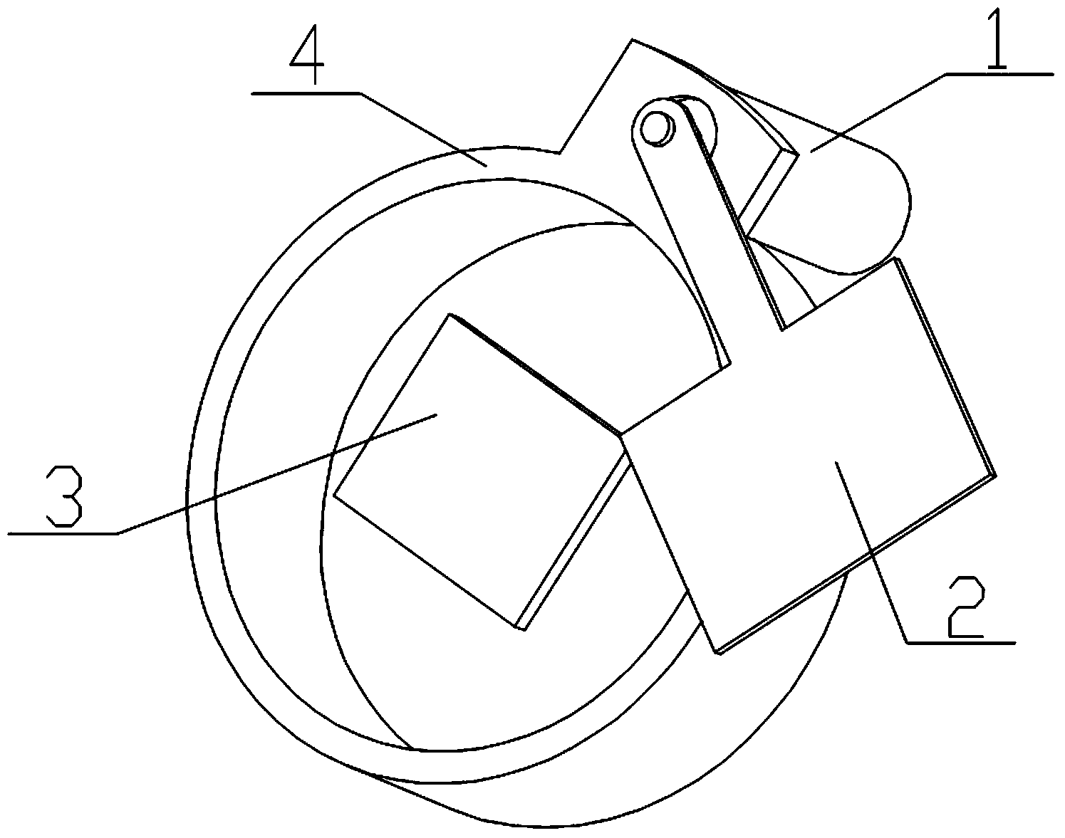
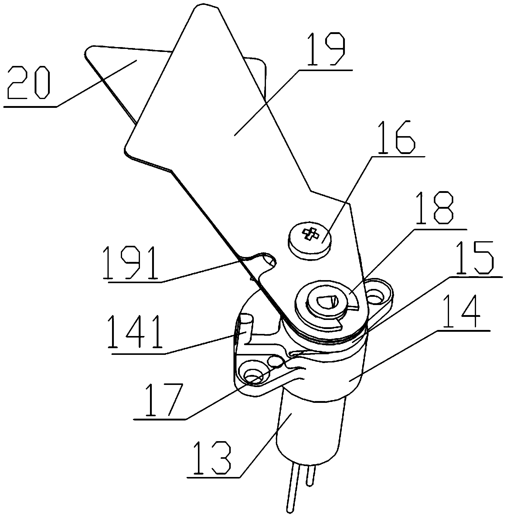
[0029] Such as image 3 and Figure 4 As shown, a focal plane shutter structure includes a motor 13, a motor base 14, a spring 17, a shutter fixing plate 15, an upper blade 19, and a lower blade 20. The motor base 14 is fixed on the motor 13, and the motor 13 is provided with a motor shaft 131 that extends out of the motor 13 and can rotate, and the motor base 14 is provided with a through hole 142 that matches the structural position of the motor shaft 131, and the motor shaft 131 can pass through The through hole 142; the shutter fixing plate 15 is fixedly connected to the end of the motor shaft 131 away from the motor 13, the motor base 14 is located between the shutter fixing plate 15 and the motor 13, the The...


PUM


Abstract

The invention relates to a focal plane shutter structure which comprises a motor, a motor base, a spring, a shutter fixing plate, an upper blade and a lower blade. The motor base is fixed to the motor, the motor is provided with a motor shaft extending out of the motor and capable of rotating, the motor base is provided with a through hole matched with the motor shaft in structure and position, and the motor shaft can penetrate through the through hole. The shutter fixing plate is fixedly connected with the end, away from the motor, of the motor shaft, the motor base is located between the shutter fixing plate and the motor, and the motor shaft rotates and can drive the shutter fixing plate to rotate. The upper blade is arranged on the lower blade in a stacked mode, and the upper blade and the lower blade are fixed to the upper surface of the shutter fixing plate through a snap spring and a screw. A boss is arranged on the motor base, the spring is arranged on the motor shaft in a sleeved and surrounding mode, one end of the spring is fixed to the motor base, and the other end of the spring is clamped on the boss. The focal plane shutter structure is driven by the motor, the structure of the double blades is adopted, the size of the shutter driving device is greatly reduced, the shutter stability is improved, and miniaturization of electronic imaging equipment is ensured.

Description

technical field [0001] The invention relates to the field of electronic imaging equipment such as a camera, a video camera, a camera phone, an infrared thermal imager, and in particular to a focal plane shutter structure. Background technique [0002] In recent years, the size of the camera module has shrunk with the development of technology, but the size of the shutter driver still restricts the size of the camera module, especially in the infrared industry. In the infrared industry, due to the limitation of the chip manufacturing process, the size of the focal plane is relatively large, and the size of the shutter is several times that of the visible light shutter, resulting in a large size of the entire infrared camera. The traditional shutter driving device mostly uses a motor to drive a single blade to rotate (such as figure 1 shown) or the solenoid valve drives the vane movement (such as figure 2 shown) to realize the opening and closing of the shutter. [0003] ...

Claims


Application Information

Patent Timeline
IPC IPC(8): G03B9/10
Inventor 孙同波孙承阳孙中华黄星明
Owner IRAY TECH CO LTD
Why Eureka
Try Eureka