Tunnel cable fault inspection system and method

A cable and tunnel technology, applied in the field of tunnel detection, can solve problems such as failure to detect whether the damaged fixing fixture on the appearance of the cable falls off, and cannot prevent the danger of cables, etc., achieving simple structure, ensuring driving safety, and accurate collection results. Effect

Active Publication Date: 2014-11-26
HEBEI HUAHENGXIN COMM TECH
View PDF6 Cites 18 Cited by
  • Summary
  • Abstract
  • Description
  • Claims
  • Application Information

AI Technical Summary

Problems solved by technology

[0005] At the same time, the above-mentioned detection of the cable can only detect the performance indicators of the cable, such as whether there is signal transmission, whether there is a standing

Method used


Image

  • Tunnel cable fault inspection system and method
  • Tunnel cable fault inspection system and method
  • Tunnel cable fault inspection system and method

Examples


Embodiment 1

[0039] Embodiment one A tunnel cable fault inspection system and corresponding tunnel cable fault inspection method

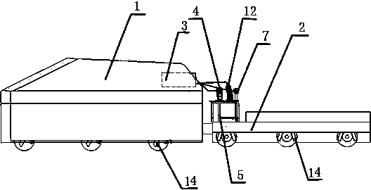
[0040] In this embodiment, the tunnel cable fault inspection system refers to figure 1 ,it includes:

[0041] (1) Automatically running inspection vehicle. In this embodiment, a railway fuel locomotive is used as the inspection vehicle, and the maximum speed can reach 80KM / h. Such as figure 1 As shown, the inspection vehicle includes a front 1 and a rear 2, and wheels are provided on the lower surfaces of the front 1 and the rear 2. In this embodiment, the headstock 1 is a carriage structure, and a control unit 3 wirelessly connected to the main control center of the control room is fixed inside; the tailpiece 2 is a flat plate, which can be used as a mounting base for installing other components.

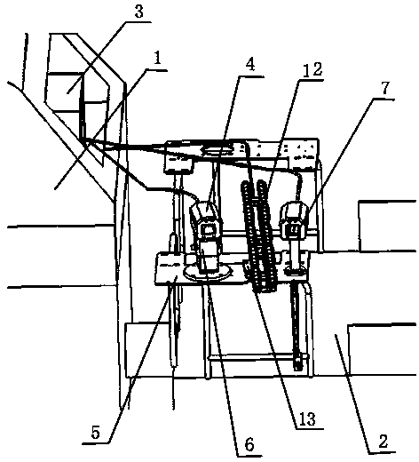
[0042] (2) An information collection unit for inspecting the cables in the tunnel. The information collection unit in this embodiment is such as figure 2 As...

Embodiment 2

[0068] Embodiment two A tunnel cable fault inspection system and corresponding tunnel cable fault inspection method

[0069] In this embodiment, the tunnel cable fault inspection system refers to figure 1 ,it includes:

[0070] (1) Automatically running inspection vehicle. In this embodiment, a railway fuel locomotive is used as the inspection vehicle, and the maximum speed can reach 80KM / h. Such as figure 1 As shown, the inspection vehicle includes a front 1 and a rear 2, and wheels are provided on the lower surfaces of the front 1 and the rear 2. In this embodiment, the headstock 1 is a carriage structure, and a control unit 3 wirelessly connected to the main control center of the control room is fixed inside; the tailpiece 2 is a flat plate, which can be used as a mounting base for installing other components.

[0071] (2) An information collection unit for inspecting the cables in the tunnel. The information collection unit in this embodiment is such as figure 2 As...


PUM


Abstract

The invention discloses a tunnel cable fault inspection system and method. The tunnel cable fault inspection system comprises an automatic running inspection vehicle and a locating unit for locating the inspection vehicle, wherein a control unit in wireless connection with a main control center of a control room, a signal acquisition unit for inspecting a cable in a tunnel, an illuminating unit for providing illumination for the signal acquisition unit, and a power supply unit for providing electrical energy are fixedly arranged on the inspection vehicle; the signal output end of the signal acquisition unit is connected with the signal input end of the control unit, the power supply unit is connected with the power ends of the control unit, the signal acquisition unit and the illuminating unit respectively; the signal output end of the locating unit is connected with the control unit. The tunnel cable fault inspection system has a simple structure, can automatically and completely inspect cables without requiring a worker to enter tunnels, can timely find cables with damaged appearance and cables with opened or falling clamps, and can timely maintain the cables to ensure travelling safety. The tunnel cable fault inspection system is suitable for inspecting cables in various road and bridge tunnels.

Description

technical field [0001] The invention belongs to the field of tunnel detection, and relates to a tunnel cable detection device, in particular to a tunnel cable fault inspection system, and at the same time, the invention also relates to a corresponding tunnel cable fault inspection method. Background technique [0002] Currently, tunnels are an important part of transportation. The tunnel is generally equipped with various cables such as communication cables and power supply cables. After these cables have been in operation for a long time, failures such as cable damage and shedding may occur due to various reasons, such as the pressure caused by vehicles driving at high speed in the tunnel. Wave and micro-pressure fluctuations and shocks, or damage to cables caused by natural disasters such as water seepage, freezing and thawing, once there is a problem with the line, it will have a serious impact on driving. [0003] In order to prevent the impact of cable failures on the ...

Claims


Application Information

Patent Timeline
IPC IPC(8): G07C3/00
Inventor 董志刚乔雷郑晓
Owner HEBEI HUAHENGXIN COMM TECH
Why Eureka
Try Eureka