Converter cooling system

A technology of heat dissipation system and converter, applied in output power conversion device, cooling/ventilation/heating transformation, electrical components, etc., can solve the problem of waste of cooling medium, and achieve the solution of condensation, small and stable total demand The effect of air temperature

Inactive Publication Date: 2017-06-13
CSR ZHUZHOU ELECTRIC LOCOMOTIVE RES INST
View PDF5 Cites 0 Cited by
  • Summary
  • Abstract
  • Description
  • Claims
  • Application Information

AI Technical Summary

Problems solved by technology

In addition, when the cooling medium flow rate is too large, it will cause waste of cooling medium

Method used


Image

  • Converter cooling system

Examples


Embodiment Construction

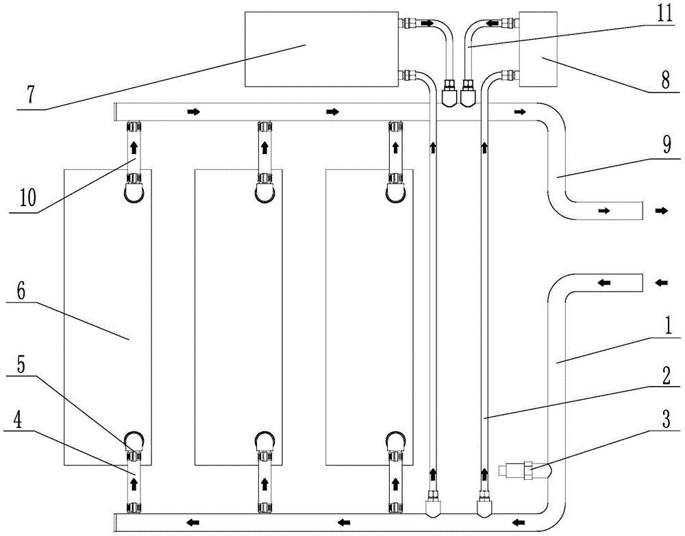
[0022] The present invention will be further described below in conjunction with the accompanying drawings and specific embodiments.

[0023] like figure 1 Shown is a specific embodiment of the heat dissipation system of the converter of the present invention. In this embodiment, the heat dissipation system mainly includes a main water inlet pipe 1 connected to a cooling water source, a large-diameter water inlet pipe 4 connected between the main water inlet pipe 1 and a high-power heat dissipation device 6; The small-diameter water inlet pipe 2 between the power cooling devices 7; and the water outlet pipe 9. Among them, the outlet pipe 9 is connected to the outlet of the high-power heat dissipation device 6 through the branch pipeline 10, and the outlet pipe 9 is connected to the outlet of the low-power heat dissipation device 7 through the branch pipeline 11, and then the fluid medium carries heat and is discharged from the outlet of the outlet pipe 9. device. Here, the ...


PUM


Abstract

The invention discloses a heat dissipating system for a current transformer. The heat dissipating system comprises a main water inlet pipe connected with a cooling water source, large-diameter water inlet pipes connected between the main water inlet pipe and high-power heat dissipating devices, small-diameter water inlet pipes connected between the main water inlet pipe and low-power heat dissipating devices, and water outlet pipes connected with outlets of the high-power heat dissipating devices and outlets of the low-power heat dissipating devices through branch pipelines. Heat is carried by fluid media to be exhausted to be exhausted of current transformer equipment. The number of the high-power heat dissipating devices and the number of the low-power heat dissipating devices are respectively at least one. All the heat dissipating devices are connected with the main water inlet pipe through the large-diameter water inlet pipes or the small-diameter water inlet pipes. The positions of the low-power heat dissipating devices are higher than the positions of the high-power heat dissipating devices. The heat dissipating system can reduce total flow of the cooling media to the maximum degree while meeting the requirements for heat dissipation of all the heat dissipating devices.

Description

technical field [0001] The invention relates to a heat dissipation system, in particular to a heat dissipation system of a converter used for heat dissipation of the converter. Background technique [0002] In recent years, with the continuous development of power electronics technology, converter technology has become increasingly mature, making converters widely used in various industries. Then comes the heat dissipation problem of the converter, especially for the converter with small space, large capacity and multi-function, how to design an effective, simple and reliable heat dissipation system is very important. [0003] The heat dissipation systems currently used mainly include air-cooled heat dissipation systems and water-cooled heat dissipation systems. Especially in the heat dissipation of the converter, air cooling is often used for heat dissipation. Air-cooled cooling has high heat dissipation efficiency, but in order to increase the heat dissipation area, it g...

Claims


Application Information

Patent Timeline
Patent Type & Authority Patents(China)
IPC IPC(8): H02M1/00H05K7/20
Inventor 周文勇史虎李滔向言丰丁祖辉
Owner CSR ZHUZHOU ELECTRIC LOCOMOTIVE RES INST
Why Eureka
Try Eureka